Because of the Thanksgiving holiday in the U.S., TI E2E™ design support forum responses may be delayed from November 25 through December 2. Thank you for your patience.

This thread has been locked.

If you have a related question, please click the "Ask a related question" button in the top right corner. The newly created question will be automatically linked to this question.

TPS25981: EN control of TPS259814A after overload removal

Part Number: TPS25981

I am checking the overcurrent protection operation of my prototype board with TPS259814A.
After the overcurrent protection works, the TPS259814A automatically returns to steady state when the load is removed.
However, after that, OUT does not turn off even if EN is set to 0V.
After setting IN to 0V and then supplying power again, OUT can be controlled by EN.
Is this behavior in accordance with the specifications?

  • Hi IZUMI,

    Do you have some waveforms?

    Regards

    Kunal Goel

  • Hi Kunal,

    Thanks for reply.

    I attach two waveforms.

    1. Waveform when EN is changed to 0V before an overcurrent event.

    2. Waveform when EN is changed to 0V after the overload is removed.

    Regards

    Izumi

  • Hi Izumi,

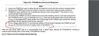
    This could be related to some noise on the ITIMER pin. Is it possible to follow this recommendation and try experiment again?

     ,

    Also please share schematic for review. 

    Regards

    Kunal Goel

  • Hi Izumi,

    This could be related to some noise on the ITIMER pin. Is it possible to follow this recommendation and try experiment again?

     ,

    Also please share schematic for review. 

    Regards

    Kunal Goel

  • Hi Kunal,

    Thanks for the suggestion.

    I added a 30kΩ resistor between the ITIMER pin and the CITIMER and tried the experiment.
    But the result did not change.

    Attached is the schematic. Please review the schematic.

    Regards

    Izumi

  • Hi Izumi,

    Schematic looks fine. 

    1. Do you see VOUT going negative during overcurrent test?

    2. Can you also probe ITIMER and dvdt pin for the overload and EN low case. Please capture for the both case when 30K is there and not there.

    3. Can you also try overload experiment again by adding more cap at input maybe 22uF and then check if issue is still there. Basically I want to prevent that VIN drop during overload case. Just want to see if VIN drop is gone then also do we see the issue. 

    4. You are adding 30K like this, right?

    Regards

    Kunal Goel

  • Hi Kunal,

    1. Do you see VOUT going negative during overcurrent test?

    VOUT is stay 0V during overcurrent test.

    2. Can you also probe ITIMER and dvdt pin for the overload and EN low case. Please capture for the both case when 30K is there and not there.

    EN is driven High when starting overload test.
    And EN is driven Low during the overload test.

    • 30K is there.

    • 30K is not there.

    3. Can you also try overload experiment again by adding more cap at input maybe 22uF and then check if issue is still there. Basically I want to prevent that VIN drop during overload case. Just want to see if VIN drop is gone then also do we see the issue. 

    Tested with 47µF added, VIN drop is reduced and no more issues occur.

    Am I correct that the problem was caused by the input voltage dropping below the recommended operating voltage due to overload?

    4. You are adding 30K like this, right?

    Yes, That is right.

  • Hi Izumi,

    Looks like VIN fluctuations beyond recommended max was causing some issue. Please keep 47uF input cap in your design. 

    Regards

    Kunal Goel