This thread has been locked.

If you have a related question, please click the "Ask a related question" button in the top right corner. The newly created question will be automatically linked to this question.

UC2842A: Slop Compensation

Part Number: UC2842A
Other Parts Discussed in Thread: UC2844A

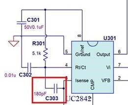
Customer fund that the duty cycle would be unstable at quite light load and certain input condition. However, when C303 is added between Pin3 and Pin4, the problem is gone. We'd like to know the knowledge behind why this cap is able to solve the problem and is this related to the slop compensation? Is there application note talking about this cap in Flyback application?

Regards

Brian 

  • Hi Brian,

    Current mode controllers need a slope compensation for steady state duty cycles higher or equal than 50%. Current mode controllers will face a stability issue at duty cycles higher than 50% due to the fact that the reference voltage coming from the output of the E/A needs to be sloped down to allow the PWM latch to be reset correctly and avoid instability. It also improves the noise immunity of the PWM comparator inside the IC. If you connect a capacitor between RT/CT and CS pin, you are DC blocking the oscillator signal coming from RT/CT and you would have switched to voltage mode control. I recommend to follow the slope compensation criteria design specified in this datasheet, section 9.2.2.10.2:

    Datasheet

    For more detailed information about slope compensation, please refer to the following applications note:

    slua257.pdf

    slua110.pdf

    If you have any further questions, please let me know replying to this thread.

  • Hi Alva,

    1.If i am using 2844A, the duty is limited below 50%,is there still need for slope compensation?

    2.Unstable only occur when light load, DCM, and duty still not exceed 50%, is this related to slope comensation?

    3.oscillator signal is sended to PWM flip-flop in IC, CS pin current singal is moving to current comparator in IC, how is this capacitor DC blocking oscillator signal to CS pin? If so,how is this switched to voltage mode control? could you please describe more about it?

    Thanks!

  • Hi Pin-chih

    1. UC2844A has a maximum duty cycle of 50%, so slope compensation is not needed as you pointed out. It probably means that at light load, you are facing a noise problem. At light load, the primary peak current is low, and it would be comparable with the turn-on current peaks coming from the parasitic of the MOSFET when is turn-on. Meaning that PWM current comparator inside the IC would be reading either the turn-on peaks or the primary peak current to latch the PWM signal.

    2. I recommend the following debug:

    a. Measure the Isense-Ground voltage at the IC pins without the C303 180pF and with the C303 180pF. Do you notice a difference between both voltage signals? The turn-on peaks at the beginning of the switching period are higher when C303 is not connected? 

    3. Adding a capacitor between RT/CT and Isense pins is not the common way to improve the filtering of the primary current sense voltage. The correct way to do it is adding an RC filter (your schematic has one) and an external leading-edge blanking to delay the voltage at Isense pin some nanoseconds. Adding a capacitor would lead to an offset (DC blocker) in your current sensed signal. But in this case, it would just lead to improve the filtering. 

    I recommend using tip and barrel method when measuring the Isense-Ground voltage with a scope probe. Remove the cover tip and ground lead and use a tip and barrel connector. Please see picture below.

    If you have any further questions, please let me know replying to this thread.