


Dear Sir
【 Question 1 】 According to the GRAYSCALE (GS) Function (PWM Control) in the specification book (grayscale function)
The faster the frequency of GSCLK, the faster the frequency of OUT, and every 65535 cycles of GSCLK is equal to 1 cycle of OUT. The ratio of the frequency of GSCLK to the PWM frequency of OUT is 65535:1.
Assuming this ratio holds, the maximum frequency of GSCLK is known to be 33MHZ, and the PWM frequency at this time is 503HZ. Is this the calculation? If not, how is the ratio calculated?
[Question 2] In our actual measurement, the frequency ratio of GSCLK and OUT is fixed at 512:1. Can this ratio be changed?
According to my understanding, GS Counter seems to be a register, with+1 for every GSCLK generated. When the GS Counter count is full, OUT generates a PWM cycle.
According to the actual measurement (the frequency ratio of GSCLK and OUT is fixed at 512:1), the overflow value of GS Counter is 128, which means that,
For every 512 cycles generated by GSCLK, PWM generates 1 cycle,
In other words, for every 65535 cycles generated by GSCLK, PWM generates 128 cycles.
This corresponds to the actual measured ratio of 512:1. Can this overflow value be set and changed?
In the specification, GS Counter did not provide a detailed description. If the above understanding is incorrect, please explain what GS Counter is and how it relates to GSCLK and OUT frequencies?
What is the minimum input frequency of GSCLK? I understand that there is no mandatory requirement for a minimum input frequency, but if this frequency is too low, it will affect the frequency of OUT and the update speed of LED grayscale, etc.
What is the highest input frequency of GSCLK? I understand that there is no mandatory requirement for the highest input frequency, but it is limited by the rise time and fall time of OUT.
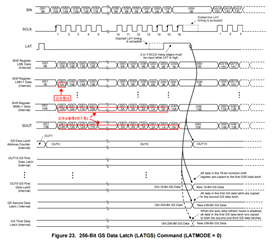
【 Question 6 】 It was found that there is an error in Figure 23, with the incorrect serial number of the data. Some data should not be A, but should be B.
【 Question 7 】 The issue of uneven LED brightness gradient function at low frequencies.
GCLK=2Mzh, PWM=2KHZ This is OK.
GCLK=1Mzh, PWM=1KHZ, the human eye looks not very smooth, and can see the brightness changing stage by stage.
GCLK=100KHZ, PWM=100HZ, the human eye looks particularly uneven and obvious, with a slow rate of change, changing brightness every 0.6 seconds.
My understanding is that the reason is the internal Auto Data Refresh Function function of TCL59482. This function solves the problem of "setting the brightness when low frequency (GSCLK<1MZH) will instantly light up". The principle is that even if the brightness is set to the LED chip, the LED chip does not immediately update the brightness, but only automatically updates the brightness inside the LED chip when the current PWM cycle's 65536th GSCLK occurs. This mechanism solves the problem of "setting brightness at low frequencies will instantly light up". However, due to the need to wait for 65536 GSCLK occurrences before updating brightness, the speed of updating brightness is limited by the speed of GSCLK. This leads to a slower speed in updating the brightness of LED chips below a certain frequency (GSCLK=2MHZ), which appears uneven.
Is this my understanding? How to solve this problem? If the ratio between the PWM frequencies of GSCLK and OUT can be adjusted, it should be possible to adjust it to an appropriate ratio to solve this problem.
