This thread has been locked.

If you have a related question, please click the "Ask a related question" button in the top right corner. The newly created question will be automatically linked to this question.

LM25184: Flyback eval board output loses regulation

Part Number: LM25184
Other Parts Discussed in Thread: , LM25183,

I modified LM25184EVM-S12 per correspondence with Youhao so that I could run at 24V in and 24 V out. See below.

Thank you for consider the LM25184.  You can modify the output by raising the resistor at the FB pin, but you will have to replace a few more parts:  

  • C9 on the EVM is just 16V rated.  You need to change it to be able to handle your new output.  
  • D3 is a 13V Zener and it will be damaged if you simply raise the output voltage.  Consider to replace it with a 26V Zener.
  • C6 and C7 are 25V rated, too close to your 24Vout.  Consider to change to 50V rated to get margin.
  • D1 is 60V rated.  You may consider to change it with a 100V rated diode.
  • D2 is 20V rated and it would be damaged by the flyback voltage if Vout is changed to 24V.  Suggest to change to a 32V Zener.

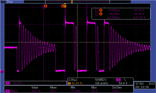
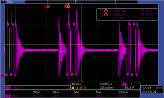
I connected 177 ohm, 8W resistor and let it run.  Iout was .136A.  Vout = 24.1V.  I did 3 runs and on each run at approx 20 min into the run, the output voltage stepped up to 25.5 V and .144A.  I monitored the SW node TP2 with a scope during the run. Attached are the waveform before the problem and after.  The first is before and looks nice and repetitive, and the next 2 are after at different sweep rates.  They look like burst mode or something.  Can you please tell me why this is happening?  The current is very low.

  • Hi John,

    I will need a couple of days to look into this and will reply by the end of the day Thursday (PST). In the meantime, can you provide a schematic of your updated design from the previous recommendations?

    Best regards,

    Ridge

  • Hi John,

    Sorry to hear, but did you make all the modifications that I suggested?

    Anyway, those mods were to get 24Vout on the standard EVM as a quick proof of concept, but the circuit may not be optimized for your application.  Note that the factory installed transformer is designed to produce 12Vout.   If you check our design calculator, the min inductance should be >12.6uH for 24Vout if you still use 1:1 turns ratio, while the EVM transformer has 7uH.  Change to a different transformer with 13uH should improve the performance.  Would you please update the transformer in accordance?

    Thanks,

    Youhao

  • Eval Modifications.pdf Attached is the schematic showing the changes that were made.

    For some reason when increasing R5 to get to 24Vout I had to put a load that was about 177 ohms.  If it was 330 ohms or more the output would just float up to 40V.  I figured this might be due to some minimum current that it needed somewhere so I changed from 330 to 177 ohms and it got me to 24.1Vout.  Youhao replied also and said to change to a 1:1 transformer with 13 uh.  I will try to find that but don't know how to start - maybe I have to contact Coilcraft?? I would like to know what it is doing right now and to know why going to 13 uh will get it back to normal.  This is our first time with a flyback converter so we are very limited and don't understand fully what changes to the circuit need to be made or way in order to optimize this for 24V 1A.

  • Hi John,

    Your mods look good.  Now you need to replace the transformer.

    To answer your question:  The IC has a min load requirement, which is estimate after I answer your question about Lmag selection. \

    The minimum inductance is required by the IC to operate properly.  Please see the datasheet info:

    Basically, the 420ns is the delay time for the FB pin to sense the output.  The proper FB sensing moment is also the moment when the secondary current decays to zero.  If you have a smaller inductor, the secondary current will decay faster and falls within this min off time, and the sensing will be affected by noise and hence result in unstable switching.  

    Note that the IC has a min peak current limit, too, which is 20% of the max peak current limit.  That means the primary current is always at or above the min peak current limit.  At light load, it reaches the min peak current but the IC flold back the frequency to meet the output load condition under light load. The secondary decay time would be:

    tsec = Lsec * Iminpk/Vout,  where Iminpk is 0.82A for the LM25184, or 20% of its 4.2A max peak.

    Lmag = Nps^2 * Lsec

    You can see a smaller Lmag will lead to a smaller tsec.   The selection of Lmag is required such that tsec is >= 420ns. 

    Now, the min load requirement: Since the current will always reach Iminpk or higher, the power to be delivered to the secondary can be estimated as:

    Po = 0.5 * Fswmin * Lmag * Iminpk^2

    Where Fswmin=12kHz typ, and Iminpk = 0.82A typ.  This power must be dissipated by your load or a dummy load to prevent the net charge accumulation in the output capacitors. If there is a net charge accumulation during switching, Vout will rise.

    Hope this clarifies.

    Thanks,

    Youhao

  • Youhao, thank you for the detailed information.  I see based on your min off time 420ns and the Iminpk of .82A how I need >12 uh.  I need to spend some time on this fresh in the morning but in the meantime, where are these Iminpk of 20% in the data specs.  I can't seem to find this.  Also, I still don't know why the output voltage goes high with a load resistance greater than 330 ohms.  Using the formula for PO above Po = 0.5 * Fswmin * Lmag * Iminpk^2, that gives me a power of .028 W which at 24Vout I should be able to load with 20kohm and still be OK.  Can you help me understand that?

    Thanks - John

  • Hi John,

    Your issue with the load is mostly related to running into the 420ns.   The 20% is in the datasheet, at the end of section 7.3.2.  Here I copied and paste below from the LM25184-Q1 datasheet, because the LM25184 industrial version datasheet has a typo,  still showing LM25183's number there.  Thank you for helping us find a datasheet typo.  We will need to correct it in our next revision of the datasheet.

    Thanks,

    Youhao