This thread has been locked.

If you have a related question, please click the "Ask a related question" button in the top right corner. The newly created question will be automatically linked to this question.

TPS25750: Negotiation issue between TPS25750 and BQ25792

Part Number: TPS25750
Other Parts Discussed in Thread: BQ25792, USB-PD-CHG-EVM-01, TPS25751

Hi,

I received an inquiry regarding the negotiation issue between TPS25750 and BQ25792 from our customer. So, I would be grateful if you could give me some advice on the following.

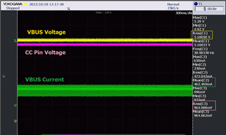
When a 5V/1.5A source device was connected to TPS25750D with the prototype board, which was in the following status.
It seems to be recognizing charger current 1.5A as intended, but the actual USB supply current is only 0.5A.
- CC pin voltage was 0.964Vrms
- Cc1PinState of 0x69 TYPEC_STATE Register was 04h (1.5A Advertisement detected (Sink only))

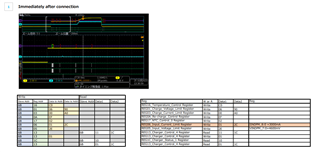
The status of the charger IC BQ25792 shows as follow.
It seems that the information on the current value determined by TPS25750D through negotiation with a source device wasn’t correctly conveyed to BQ25792.
- VINDPM_7:0 of REG05_Input_Voltage_Limit Register was 4.7V
- IINDPM_8:0 of REG06_Input_Current_Limit Register was 500mA

In addition, some USB Type-C PD AC adapters and mobile batteries from other manufacturers with a power supply capacity of 15W to 30W couldn't be negotiated and the power supply would be cut off.
When checking the behavior, it seems that it was flowing a current higher than the one determined through negotiation with a source device.

For example, the negotiation result of TPS25750D was 9.00V/2.00A when using 18W(9V/2A) AC adapter.
However, the status of the charger IC BQ25792 shows as follow.
- VINDPM_7:0 of REG05_Input_Voltage_Limit Register was 4500mV
- IINDPM_8:0 of REG06_Input_Current_Limit Register was 2000mA or 3000mA
It is thought that it changes to 2A and 3A depending on the timing because negotiation is performed again after negotiation fails.

Could you please answer the following questions?

<Questions>
Q1.
Have you ever experienced such symptoms?

Q2.
Can TPS25750D support Type-C Current 1.5A?

Q3.
Is it the charger IC BQ25792 that controls the current so that it doesn't flow more current than the result of negotiation?

Q4.
How long does it take for BQ25792 REG06_Input_Current_Limit Register IINDPM_8:0 to change the current value setting from the negotiation result?

Q5.
What determines the timing at which BQ25792 flows current?

Additionally, I would like to share the detailed information (bin file, schematic, etc.) with you via an e-mail.
Please feel free to contact me if you have any questions.

Best regards,
Kato

  • Kato,

    Here are answers to your questions:

    1.  I have replicated this issue on an EVM.  The current limit for type C connections is always set to 3A instead of updating based on the type C connection state.

    2.  The TPS25750D does support 1.5A type C current, but the communication between the BQ25792 and TPS25750 is not correct.

    3. The BQ25792 is the device that controls the current limit, butthe TPS25750D makes the decision and is supposed to update the BQ25792

    4. The IINDPM is written immediately after the PS_READY is sent from the SINK.  The delay is in the 10-100 uS region

    5. The TPS25750 updates the IINDPM and VINDPM of the BQ25792 immediately after it negotiates the sink contract. 

    I do not think that a schematic or project is necessary.  I have been able to replicate the issue on my own.  I will be submitting this as a bug to our internal group, but it has a fairly long lead time to get fixed on this part.

    Do you have a MCU in your system that has access to our host interface?  I can help you generate a simple MCU routine to overwrite this issue if you do.

    Regards,

    Chuck

  • Hi Kato,

    I have spoken with our marketing team and we have a pin for pin cost parity part that will be releasing soon that will fix this bug, so it is very unlikely that we will have resources to fix this particular bug in the short term.

    What is your timeframe for production?

    Regards,

    Chuck

  • Hi Chuck-san,

    Thank you for the very important information.

    I'm very surprised there was a known bug.
    It would be helpful if you could support me to avoid this bug because TPS25750 can be configured via I2Cs bus with uC.
    However, uC goes into SUSPEND mode and cannot communicate with TPS25750 when the product is powered off. Just like a smartphone, the battery needs to be charged even when the product is turned off. Therefore, communication from uC to TPS25750 is impossible when the power is off due to reboot (ship mode release, etc.), making it difficult to avoid this bug.
    So, I would like to consult with you, but is there a possibility that this can be avoided by changing the bin file? If it is possible, I would like to request that you take action.
    The deadline for changing the bin file is October 31st.

    Your quick response would be greatly appreciated. So, please feel free to contact me if you have any questions.

    Best regards,
    Kato

  • Hi Kato,

    Chuck is currently out of office, but please expect a response from marketing here in regards to Chuck's comments. I am still diving into your email as well.

    Do you have a MCU in your system that has access to our host interface?  I can help you generate a simple MCU routine to overwrite this issue if you do.

    If this is desired, Chuck may be able to still get this when they return, but I can not speak for them as they may not be able to.

    Thanks,
    Field

  • Hi Field-san,

    Thank you for your reply on behalf of Chuck-san.

    Our customer is considering again whether a workaround which you would suggest can be implemented to TPS25750 or not. So, could you please generate a simple uC routine to overwrite as soon as possible?

    By the way, I would like to ask you a question regarding Chuck-san's Q4 and Q5 answers above.
    There were cases where TPS25750 sank the current before PS_READY was sent from the SOURCE device when analyzing USB bus with USB protocol analyzer. This is status before TPS25750 updates BQ25792's IINDPM and VINDPM and it seems there is a possibility that TPS25750 can sink 3A which is the default value.
    Have you ever experienced such symptoms? Additionally, please let me know any workarounds.

    The deadline for changing the software is October 31st. So, it would be helpful if you could assign someone on behalf of Chuck-san if possible.

    Best regards,
    Kato

  • Hi Kato-san, 

    You can use 4CC command 'I2Cw' to overwrite the BQ register through the PD as an I2C pass through (see excerpt from the Technical Reference Manual below):

    In order to send a 4CC command, follow the sequence described below (this applies to I2Cw and I2Cr):

    By the way, I would like to ask you a question regarding Chuck-san's Q4 and Q5 answers above.
    There were cases where TPS25750 sank the current before PS_READY was sent from the SOURCE device when analyzing USB bus with USB protocol analyzer. This is status before TPS25750 updates BQ25792's IINDPM and VINDPM and it seems there is a possibility that TPS25750 can sink 3A which is the default value.

    Do you have a PD log along with I2C scope capture of the I2C traffic between TPS25750 and BQ25792 of this occurrence? What is the test scenario in this case where TPS25750+BQ25792 is sinking current prior to PSReady? Was there already a PD contract in place before a new contract was negotiated? How about the source device capabilities? 

    I'll follow up tomorrow with an example of I2Cw to re-configure register 0x05 (VINDPM) and 0x06 (IINDPM) of the BQ25792. 

    Thanks and Regards,

    Raymond Lin

  • Hi Raymond-san,

    Thank you for your reply on behalf of Chuck-san.

    Please give me a little more time as I am compiling a document regarding your questions.

    Best regards,
    Kato

  • Hi Raymond-san,

    I have compiled a document in response to your questions, so please confirm the attached file "TPS25750_Negotiation_Issue.pdf".
    Although not mentioned in the documentation, similar symptoms have been observed in many other products.

    I hope that the root cause of this issue will be clarified and that you will be able to let me how to improve it as soon as possible.TPS25750_Negotiation_Issue.pdf

    Best regards,
    Kato

  • Hi Kato-san, 

    Can you also provide a JSON config the customer is using when they're encountering the current draw issue? I will try to replicate it on my end using the USB-PD-CHG-EVM-01 so I can debug it further. 

    When the TPS25750 is sinking current prior to PSReady, did the TPS25750 already configured the IINDPM register of BQ25792 or does the I2C write to IINDPM (reg 0x06 of BQ25792) occur after PSReady? To be specific, at the moment you captured below:

    Thanks and Regards,

    Raymond Lin

  • Hi Raymond-san,

    Thank you for your continuous support.

    Our customer has used a bin.file generated by your colleague, not a project file (.json). I would share that bin file with you.
    Unfortunately, I can't upload a bin file, so I changed the file extension from .bin to .pdf. When using it, please change the extension to .bin.

    For your additional questions, I would explain the entire process in the chronological order as follows.

    1. TPS25750 writes 3000mA to IINDPM_8:0 before negotiation is completed
    2. Negotiation completed
    3. VBUS voltage and current increase, current continues to flow at 2.8A
    4. SOURCE device sends PS_RDY to TPS25750
    5. SOURCE device sends OCP to TPS25750
    6. TPS25750 writes 2000mA to IINDPM_8:0

    It would be very helpful for me if you can replicate this issue with EVM and provide a workaround.

    20230906_GPIO_CHANGE.pdf

    Best regards,
    Kato

  • Hi Raymond-san,

    Sorry for rushing you, but please let me know if you have any updates on this issue as the deadline is close.

    Best regards,
    Kato

  • Hi Kato-san,

    Understand the urgency, I am testing on my end and should have results by next Monday. 

    If you have an Aardvark on your end, you can try running the attached batch mode example for how to setup I2Cw and re-configured the BQ25792 IINDPM (register 0x06) to 2A or any other value. You can follow up by sending 'I2Cr' to ensure 'I2Cw' executed correctly.

    Thanks and Regards,

    Raymond Lin

    Sample Batch Mode for 'I2Cw':  /cfs-file/__key/communityserver-discussions-components-files/196/I2Cw_5F00_Configuring_5F00_BQ25792_5F00_IINDPM_5F00_Register_5F00_Example.txt

    Sample Batch Mode for 'I2Cr': /cfs-file/__key/communityserver-discussions-components-files/196/I2Cr_5F00_Configuring_5F00_BQ25792_5F00_IINDPM_5F00_Register_5F00_Example.txt

  • Hi Raymond-san,

    Thanks for providing the batch files.

    I would like to confirm just in case, but is my understanding correct that the purpose is to check whether these can be re-configured using the 4CC commands I2Cw and I2Cr?
    I think the timing of re-configuring is important when actually implementing the workaround, so I'm looking forward to getting an update on Monday.

    Best regards,
    Kato

  • Kato,

    The 4CC commands that Raymond has provided show the I2C transactions that will allow an External MCU to change in IINDPM register to set the current limit appropriately.

    The MCU system will need to process the I2Cs_IRQ, read the status register of the PD controller, determine that a 5V/1.5A PDO has been negotiated and then change the IINDPM register using the command the Raymond provided.

    Regards,

    Chuck

  • Hi Chuck-san,

    Thank you for the information.

    You would mention that the status register of the PD controller is read using the timing when /I2Cm_IRQ, which is an interrupt signal sent from BQ25792, is asserted low, but the uC doesn't monitor /I2Cm_IRQ. So, is there any other way to detect triggers?

    By the way, I would like to confirm just in case, have you actually tried the sample source code "I2Cw_Configuring_BQ25792_IINDPM_Register_Example.txt"? It looks like 1 byte of data is missing.
    If there is any misunderstanding, please feel free to let me know.

    Best regards,
    Kato

  • Hi Chuck-san,

    That was my misunderstanding. The signal to be monitored with the uC was /I2Cs_IRQ instead of /I2Cm_IRQ.

    I will ask our customer to confirm whether a workaround can be implemented.

    Best regards,
    Kato

  • Please let us know if they need further support

  • Hi Chuck-san,

    As you may know better than I do, I have the following two issues.

    - Communication issue between TPS25750 and the BQ25792 for PDO
    - Current sink issue that TPS25750 begins to sink the current before PS_RDY is sent from the SOURCE device and TPS25750 accepts

    For the communication issue, I have already received your advice and our customer is verifying whether the timing of reconfiguring BQ25792 is reasonable. Once I get the results, I will share the information with you.
    For the current sink issue, what will be the trigger for TPS25750 to begin sinking current? Please let me know how to begin the current sink after TPS25750 accepts PS_RDY which is sent from SOURCE device.

    Best regards,
    Kato

  • Kato,

    We are looking into the PS_RDY issue and will get back to you as soon as we have a clear answer.

    The standard requires that no significant current be synced before PS_READY is issued, so we will look at how best to address this issue.

    Regards,

    Chuck

  • Hi Chuck-san,

    Thank you for your prompt reply.

    I'm looking forward to getting an update on the PS_RDY issue as soon as possible and greatly appreciate your cooperation.

    Best regards,
    Kato

  • Hi Kato,

    The device expert is still looking into this and will provide a response when they have more information.

    Thanks,
    Field

  • Hi Field-san,

    Thank you for your continuous support.

    I'm looking forward to hearing an update on the PS_RDY issue.

    By the way, there is a separate consultation from the PS_RDY issue.
    When a 5V/1.5A SOURCE device was connected to TPS25750, although TPS25750 detected 1.5A(04h) in Cc1PinState of 0x69 TYPEC_STATE Register, BQ25792's IINDPM_8:0 of REG06_Input_Current_Limit Register was written to incorrect current information of 0.5A.
    Is this issue caused by TPS25750 hardware which is difficult to fix? Or is it due to TPS25750's rewritable firmware? If the issue is caused by firmware, I believe it is easy to fix. Could you please give me any comment?

    Best regards,
    Kato

  • Hi Kato,

    The PS_RDY issue is still being studied by our systems and firmware team and I don't have a fix date for that issue.

    For the type C current issue, that is a gap in the firmware that is not going to be fixed in the near term.  The customer can use I2Cw to update the BQ register after the initial connection using their MCU, but this is the only solution that we have in place for that issue.

    Regards,

    Chuck

  • Hi Chuck-san,

    Thank you for the information.

    For the Type-C current issue, I understand, but I'm looking forward to getting the detailed information on the PS_RDY issue.

    Best regards,
    Kato


  • We will update as soon as the study is completed.

  • Hi Chuck-san,

    Thank you for your response.

    The deadline for responding to our customer is close, so it would be very helpful if you could update as soon as possible.

    Best regards,
    Kato

  • Hi Kato-san,

    I am checking with our Marketing team.  We have a pin compatible part that is about to release that is pin compatible that addresses all of the issues that you have been facing.

    This part will be available before we will have a firmware update for the TPS25750.  Please reach out to your FAE for internal support.

    Regards,

    Chuck

  • Hi Chuck-san,

    Thank you for the information.

    I have already received information about the successor product to TPS25750 from local FAE. Is my understanding correct that you have a plan that a permanent fix will be applied and the firmware will be updated for TPS25750 issues? It would be very helpful for us if you have any plans to fix on these issues.

    Best regards,
    Kato

  • Kato,

    We do not plan to implement a permanent fix for the TPS25750.

    All future designs should move to the new device.  The new device has already been verified to have fixed these issues.

  • Hi Chuck-san,

    Thank you for the information.

    I understand.

    By the way, you mentioned that a permanent fix has been implemented in the successor product. So, is it the conclusion that the root cause of sinking current for PS_RDY issue is firmware control?

    Best regards,
    Kato

  • Hi Chuck-san,

    It is very helpful for us if you will continue to study the root cause and workaround for PS_RDY issue.

    Best regards,
    Kato

  • Hi Kato-san,

    I am passing this along to our marketing team for them to address.

    Regards

    Chuck

  • Apologies for the difficulty here and appreciate your patience as our team has worked to try and resolve these issues. As Chuck mentioned in the previous post, we have been working on releasing a new follow on device to the TPS25750, the TPS25751. An initial version of this device will be available within the next month, and we are planning to fully release it to market in 2024. 

    The TPS25751 address this issue, as well as includes other next generation features such as liquid detection and PPS. Unfortunately, with the team focusing on releasing this new device, we will not be pulling in fixes to the TPS25750 that will be addressed in the TPS25751. The TPS25751 will be pin to pin compatible with the TPS25750, so migration to the new device should be straightforward. Apologies for the confusion and the difficulties this may pose. 

  • Hi Adam-san,

    Thanks for helping me make the materials I needed.

    I understand that we will not be pulling in fixes to the TPS25750 that will be addressed in the successor product. However, the root cause of the bugs with the TPS25750 should have been found out, as the successor product will have bugs fixed.
    So, could you please share details about the root cause with me? I would like to know the trigger for TPS25750 to sink current, especially regarding the PS_RDY Issue.

    Your quick response would be greatly appreciated.

    Best regards,
    Kato

  • The issue is that the TPS25750 programs the BQ charge current to a 3A Rp value, regardless of the capabilities of the attached charger. The reason why this was never found during our bringup and testing is because all of our testing used USB-C power supplies that were capable of supplying 3A as well as USB-C PD. The problem only occurs when a standard USB-C power supply is connected, that only provides 1.5A and is not capable of negotiated a USB-C PD contract. This was a specific test case that our team had not considered when originally testing the TPS25750. Now that we are aware of this, iwe have addressed this in the TPS25751. 

    Once again, we apologies for the confusion and frustration this has brought. The TPS25751 will be addressing this item and other items found in the TPS25750. The TPS25751 will be pin to pin compatible with the TPS25750

  • Hi Adam-san,

    Thank you for the detailed information.

    I understand the root cause of the PS_RDY issue. Is my understanding correct that the Type-C current issue and PS_RDY Issue have the same root cause?
    Additionally, these issues have been already fixed in the successor product, but how were they technically improved in more detail?

    Best regards,
    Kato

  • Hi Adam-san,

    For the PS_RDY issue, I have an additional question.
    TPS25750 sinks the current before accepting PS_RDY even if only using the USB-C PD with a 3A capability. Did you not find out this symptom?

    Best regards,
    Kato

  • Is my understanding correct that the Type-C current issue and PS_RDY Issue have the same root cause?

    Yes that is correct. 

  • Hi Adam-san,

    Thank you for your quick response.

    Could you please confirm the following information?

    TPS25750 sinks the current before accepting PS_RDY even if only using the USB-C PD with a 3A capability. Did you not find out this symptom?
    Additionally, these issues have been already fixed in the successor product, but how were they technically improved in more detail?

    Best regards,
    Kato

  • Hi Adam-san,

    The PS_RDY issue has been fixed in the successor product, but how is the timing for sinking current designed in TPS25750? This will be the information we need when considering the workaround.

    Best regards,
    Kato

  • Hi Adam-san,

    Sorry for rushing you, but please let me know if you have any updates on the previous questions as it's past the deadline.

    Best regards,
    Kato

  • Hello, 

    Apologies for the delay in response. As I mentioned, the TPS25751 should address all of the issues highlighted in this thread. The device should be posted on TI.com within the next couple of weeks, so you will be able to continue your evaluation with this new device. 

  • Hi Adam-san,

    I understand that a successor product will be released soon, but I would like to know how the TPS25750 was designed and consider possible workarounds.
    Our customer doesn't have a plan to replace TPS25750 with TPS25751.

    Best regards,
    Kato

  • Hello, 

    The items outlined in this e2e thread are address in the TPS25751 through updating the I2C writes that the TPS25751 sends to the battery charger during power up and run time. 

  • Hi Adam-san,

    Thank you for your reply.

    Could you please tell us the trigger which causes the sinking current regarding the symptom that TPS25750 sinks current before accepting the PS_RDY? We would like to consider ways to avoid this issue.

    For example, the trigger timing is :
    - after TPS25750 makes a request to SOURCE device
    - after TPS25750 writes the setting values for VINDPM and IINDPM to BQ25792 registers

    Best regards,
    Kato
    *Edited and added

  • Kato,

    The issue is caused by the timing in which the PD controller updates the charger.

    The 750 firmware updates the charger as soon as the PDO request is accepted by the source, rather than waiting until PS_READY is sent.  The TPS25751 corrects this behavior by waiting for PS_READY on the type C bus before updating and enabling charging.

    Regards,

    Chuck

  • Hi Chuck-san,

    Thank you for the detailed information.

    For PS_RDY issue, Is there any way to avoid this other than modifying the firmware? For example, is there a possibility that it can be avoided by modifying the bin file?

    It would be very helpful if you could give me some advice to avoid this issue.

    Best regards,
    Kato

  • Hi Chuck-san,

    Sorry for rushing you, but please let me know if you have any updates.
    If there is a solution to this issue other than changing the firmware, we would like to try it, so any advice would be helpful.

    Best regards,
    Kato

  • Hi Kato,

    With the holidays this week, many device experts are currently out of the office. They will look into this and provide you a response when they return. Please expect some delay accordingly.

    Thanks,
    Field

  • Hi Field-san,

    Thank you for the quick reply in spite of a holiday.

    I'm looking forward to getting any updates next week.

    Best regards,
    Kato