Other Parts Discussed in Thread: LMS3635-Q1, LM1084
Hi!
I'm using TPS7A5701 chip in compination with LMS3635-Q1 DC-DC. The idea was to create a voltage follower with clean output.
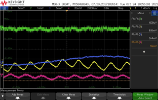
The problem is that I see a sine wave with the frequency of LMS3635 under load. Without load the results a good (at least under resolution of the oscilloscope)
At this pictture you see the output curve under 1A resistive load. The bigger the load is, the bigger is the sine noise.
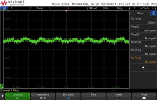
What I've already tried to do:
1. using external/internal bias
2. adding/changing type of an additional output cap
3. removing and adding 0.1uF cap parappel to REF
4. Moving ground sense (Rsense GND) connection outside of the board made the signal only a bit better.
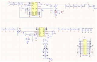
R2 in now 39k. I get 4.9V after DC-DC.
The board is 4-layer 1.0mm board.
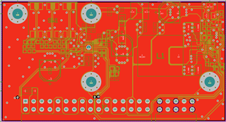
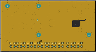
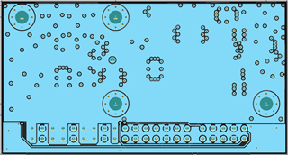
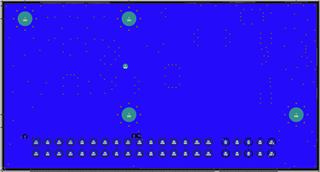
I also have almost the same board with combination of LMS3635 and LM1084 and everything works good. Any ideas?
PS I understand that I violated some PCB design considerations but I doubt that this could cause such performance issues.


 I've noticed in your layout the nets lead to a header connection through a rather long trace.
 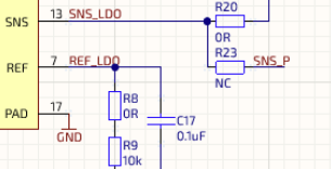 SNS and ref pins are sensitive to noise coupling in though traces functioning as antennae's
