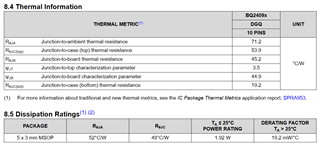
Dear TI Experts and Guru,
We have a bunch of questions here on thermal consideration of BQ24090. Please bear with me for a few minutes.
Q1: RθJA in thermal infomation and dissipation ratings of datasheet has two different values, 71.2°C/W and 52°C/W. What are the distinction between them?

Q2: Forgive me if I am asking a stupid question, for the statement as follow in Section 12.3:
"Due to the charge profile of Li-ion and Li-pol batteries the maximum power dissipation is typically seen at the
beginning of the charge cycle when the battery voltage is at its lowest. Typically after fast charge begins the pack
voltage increases to ≉3.4 V within the first 2 minutes. The thermal time constant of the assembly typically takes
a few minutes to heat up so when doing maximum power dissipation calculations, 3.4 V is a good minimum
voltage to use. "
Can I understand the above methodolgy as follow: As the threshold of precharge to fast charge is about 2.6V. The voltage drop is 5V-2.6V = 2.4V. However, the time it takes for battery to charge from 2.6V to 3.4V is typically within 2mins. Considering thermal time constant, we should instead use 5V-3.4V = 1.6V to calculate the max power dissipation for more precise evaluation. e.g. for 270mA charge current, we get 1.6V x270mA = 0.432W, and it times RθJA would lead to the temperature rise. Please point out if I am wrong anywhere.
And where do we get the thermal time constant of the assembly? Please help to point out.
Q3: Could someone shed some light on the second part? What does IBAT mean here?( Is it something like ground pin current?) What's the relationship between Vout and VBAT(How do we distinguish them)?

Thanks in advance. Would really appreciate your help. Please kindly point out if anything unclear here.
Regards,
Yuanchen

