Other Parts Discussed in Thread: UC3825,

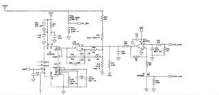
This is an applied circuit diagram, with pins 11 and 14 connected to the gate driver and full bridge MOS to obtain the final voltage output in the upper left corner. And this voltage output is not regulated, it changes at any time. Since there is no need for voltage stabilization, why not directly add PWM signals to pins 11 and 14? What is the significance of the voltage output of this application circuit being fed back, combined with external control signals, and then flowing into UC3825? What role does UC3825 play?
这是一个正在应用的电路图,其11、14脚去连接栅极驱动器和全桥MOS,得出左上角最终的电压输出。而这个电压输出不是稳压,是随时变动的。既然无需稳压,那为何不直接在11、14脚上加PWM信号?这个应用电路的电压输出最终再反馈回来,和外部控制信号一起作用后再流入UC3825,有什么意义呢?UC3825起到什么作用呢?

