This thread has been locked.

If you have a related question, please click the "Ask a related question" button in the top right corner. The newly created question will be automatically linked to this question.

LM74910-Q1: 1

Part Number: LM74910-Q1

Hi,

I want to prevent a path from overcurrent with a certain precision so I have several questions regarding the LM74910-Q1 component:

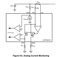
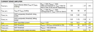
1.- What is the range of sensed voltages? I mean, between CS+ and CS-, for example if  the range is between 6 and 30mV or something like that.

2.- For calculating the minimum and maximun current limit, what are the values I have to take into account? Is the margin the one which is shown in V(SNS_SCP) with

      R(ISCP) = 0 Ohm or the one shown in IMON_ACC?

Thanks for your help.

  • Hi Jose,

    Thanks for reaching out to us. 

    Can you let us know,

    1. What is the Maximum Load current in your system ?
    2. What is the over current threshold you want to set ?
    3. Did you have a look at the design calculator available in device product folder : https://www.ti.com/product/LM74910-Q1#design-tools-simulation 
  • Hi Jose,

    The over current protection threshold can be set using Rset, Rsense and Rilim resistors and can be calculated using the formula below. Please refer to section '9.3.3.1 Pulse Overload Protection, Circuit Breaker' in the datasheet. 

    where,

    • RSET is the resistor connected across CS+ and VS
    • RSENSE is the current sense resistor 
    • ILIM is the overcurrent level

    To calculate the OCP threshold variation, you will need to look at the below parameters which is the VREF in the block diagram below,

  • Hi Praveen

    1. The Maximum load current in my system is 33 A

    2. The over current threshold I want to set is 34 A.

    3. Yes, I did. I have been doing some calculations in this design calculator but I don't know very well how the Minimum and Maximun Current Limit is calculated. This is because if the ILIM is calculated as follow: ILIM = 12 x RSET / (RSENSE x R(ILIM)) = 12 x RSET / ((VSENSE / ISCP) x RILIM)

    the variation in ILIM depends on the variation in VSNS and I understand that this variation is indicated in V(SNS_SCP) with R(ISCP) = 0 Ω if I connect ISCP to VS. But these values are different to the calculated with the design calculator.

  • Hi Praveen,

    I understand how R(ILIM) is calculated to set a desired ILIM, but how does the variation in V(SNS_TH) affect to the variation in ILIM? I mean, is there any equation you can show to me for the calculation of maximun and minimun  current limit and in which V(SNS_TH) appears?

    Thanks for your time.

  • Hi Jose,

    In the ILIM equation, the number '12' is related to V(SNS_TH) x 10 = 1.22 x 10.

    As the V(SNS_TH) threshold varies from 1.08V to 1.32V, the factor 12 in ILIM equation varies from 10.8 to 13.2. 

  • Hi Praveen,

    Where does the 10 factor come from? Could you say to me where the RILIM equation comes from?

    I want to ask you why for the Over Current Protection I have to take into account the V(SNS_TH) values (rising) instead of the V(SNS_TH) values (falling).


  • Hi Jose,

    Due to the amplifier at CS+ and CS- pins, the differential voltage across CS+ and CS- will be 0V. 

    So, RSENSE x ILOAD = RSET x ISET

    ISET is spilt into IILIM and IMON in the ration 1:9

    So, IILIM = (1/10) x ISET

    Voltage on ILIM pin is compared to VSNS_TH and when the voltage is greater than VSNS_TH rising threshold (1.22V) the TMR starts charging.

    VILIM = IILIM x RLIM 

    VILIM = (1/10) x ISET x RLIM 

    VILIM = (1/10) x (RSENSE x ILOAD / RSET) x RLIM 

    When Voltage on ILIM pin reaches 1.22V, the OCP threshold (ILIM) is hit, this means the ILOAD = ILIM when VILIM = 1.22V

    1.22V = (1/10) x (RSENSE x ILIM / RSET) x RLIM 

    So, the over current threshold, ILIM will be

    ILIM = 12.2V x RSET / (RSENSE x RLIM )

    For Over Current Protection threshold calculation you will have to take into account the V(SNS_TH) rising threshold as that is when the TMR starts charging considering an over current condition. Once the TMR starts charging, the voltage on the ILIM pin has to fall below the V(SNS_TH) falling threshold for the TMR to stop charging and come out of OCP condition. For more understanding, please refer to section ,'9.3.3 Overcurrent Protection (CS+, CS-, ILIM, IMON, TMR)' of the datasheet. 

    In the above equations do not get confused between IILIM and ILIM

    IILIM is the current flowing through the ILIM pin

    ILIM is the load current flowing thorough the power path which is considered as the over current threshold.