This thread has been locked.

If you have a related question, please click the "Ask a related question" button in the top right corner. The newly created question will be automatically linked to this question.

LM3478: LM3478MA/NOPB

Part Number: LM3478
Other Parts Discussed in Thread: UCC3803, LM5155

Dear Support Team,

I'm currently designing a circuit that requires a power supply with the following requirements:
- Input from a single 12V battery
- Two outputs around +24V and -24V (the exact value and symmetry is not so important)
- Output power : at least 35 Watts, shared between the two outputs
- No insulation required between input and outputs
- No BGA or QFN packages. If possible, avoid VSSOP.

Now, there are a lot of boost controllers available like the LM3478, which is simple enough for me.

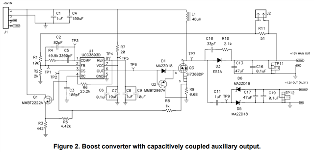
I came across an application notes for making a dual output supply out of a boost controller with a UCC3803, using a charge pump made of discrede components and capacitors:

https://www.ti.com/lit/ds/symlink/ucc3803.pdf?ts=1699154399763

Is it possible to apply the same principle to the LM3478 and stay within design requirements?

Kind Regards,

  • Hi Cyril,

    Thanks for reaching out, I assume this is the application note you are talking about: Dual Output Boost Converter (ti.com)?

    Based on this app note, this capacitively coupled bipolar output topology should be possible, given that the operating limits of the LM3478 aren't exceeded. Which shouldn't be the case given an output voltage of 24V and output power of 35W. The values of the components present in the auxiliary circuitry responsible for the generation of the negative -24V rail should however be modified.

    Before we go any further, could you please confirm that we are talking about the same topology?

    Thank you and best regards,

    Bryan

  • Dear Bryan,

    Thanks for the answer.
    Yes, this is exactly the topology I had in mind.

    Actually there is another application note I came across before this one detailing the calculation method (AN slvaej3):
    https://www.ti.com/lit/an/slvaej3/slvaej3.pdf

    Here is the first circuit draft. The component values are taken straight out of webench and duplicated for the negative output for (Input 9 - 18 V) to output (28V 5A), which is way beyond what I need.

    The MOSFET is a FDP150N10A-F102 in TO-220 package.

    The output diodes are dual 10A Schottkys in DPAK package.

    Only the series capacitor and maybe resistor values for the negative output are missing. I also think I may require a bit more capacitance on the input tank.

    Now that I found the other application note again, maybe I should just follow the provided calculation, at least if LM3478 is compatible with this topology.

    Best regards,

    Cyril

  • Hi Cyril,

    Good to know that we're on the same page! It's a big help that you're thorough in describing your thought process.
    I'll take a look at the application note and the circuit you've drafted and give you some feedback soon.

    Thank you and best regards,
    Bryan

  • Hi Cyril,

    I had a look on the application and would have some additional ideas, if you are still in the design phase.

    Regarding the component LM3478,
    we have newer controller parts within our portfolio that run with modern process and have better pricing and availability.
    For these specs, I would recommend LM5155.
    This part has same functionality and same (and even better) specs.

    There are also more reference designs, which may be helpful for your application.
    This reference design shows a two-output SEPIC design, which should be scalable for your design specs:
    https://www.ti.com/tool/PMP40488

    Please let me know if you have any open design questions.
    Best regards,
    Niklas