Because of the Thanksgiving holiday in the U.S., TI E2E™ design support forum responses may be delayed from November 25 through December 2. Thank you for your patience.

This thread has been locked.

If you have a related question, please click the "Ask a related question" button in the top right corner. The newly created question will be automatically linked to this question.

BQ25071: doesn't charge when plug in power source

Part Number: BQ25071

Hi Texas Instruments, 

I. First Topic:
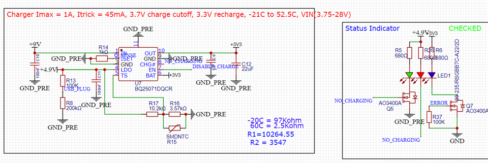
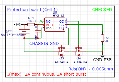
I have a charging circuit using BQ25071 to charge my 1 cell LiFePO4 battery system (which has the battery and the protection circuit). The circuit is as below. Currently, after ordering the PCB and soldered the parts, the PCB doesn't charge the battery (both via current measurement and the charge LED (a red LED) doesn't light up, but only power source detect LED ( a green LED) lights up.

Here are the tests I have tried:
1. Ensuring battery voltage is presented on the VBAT and VOUT pin of the chip when the +9V line is absent.
2. Ensuring V(TS) is within range ( in my case at 20C, V(TS) is 21% VIN, which should be fine.
3. 4.9V is working as the green LED is on and I can measure voltage on LDO pin of the chip.

4. Battery voltage is 3.34V at the time of measurement, is it not low enough to trigger recharge?

5. VOUT is 2.23V when I plug in the power source, but remove the battery. This is weird as I thought VOUT should be held at somewhere close to max charge voltage.

Noted that when I plug in the power source for the chip, I only supply 4.7V to the VIN pin (power comes from the 5V USB-C, but has 0.3V drop through a Schottky diode). Also I'm confused about the use of EN pin. Is the correct sequence every time I turn on the chip is: pull it low, then leave it high Z (or float) ? I want to utilize max charge current so I set R(Iset) = 1K. What is the default charge current if I don't perform this sequence
Please let me know if there is any reason why my board doesn't work. I really appreciate it.

II. Second Topic:

If the answer for the first question is because my battery is not low enough to trigger recharge, then is there any possible way I can force the chip to recharge. In fact, 3.3V is about 70-80% SoC of the battery, and in case user plugs in the charger, at 80% SoC for example, the board won't start charging at all, and the battery will always stuck at 80% until the battery drains below this threshold. My MCU has its own algorithm to determine when to charge and stop charging, so I prefer the BQ25071 doesn't involve in this charge control process.

Best regards,

Xander
  • Hi Xander,

    Battery voltage is 3.34V at the time of measurement, is it not low enough to trigger recharge?

    This is potentially too high as Recharge Threshold could be as low as 3.1V 

    VOUT is 2.23V when I plug in the power source, but remove the battery.

    VOUT should be approximately battery charge regulation voltage, but this can be affected by the load as well as the input current limit. Do you have a load attached?

    pull it low, then leave it high Z (or float) ?

    Pulling EN low will allow input current limit to be set by your ISET pin, you will want to keep this driven low in order to keep input current limit at ISET.

    What is the default charge current if I don't perform this sequence

    If the pin is left floating then input current limit would be limited to the USB500 current limit. If you are leaving it floating then your input current limit may be lower than your are expecting.

    I can force the chip to recharge

    A Chip recharge could be forced by driving EN high then low again. I will have to confirm this in lab.

    Best Regards,

    Juan Ospina

  • Hi Juan,

    VOUT should be approximately battery charge regulation voltage, but this can be affected by the load as well as the input current limit. Do you have a load attached?

    There is a mosfet in my board which engage or disengage the load from the battery. I realize when there is no battery connected to the system, regardless load is connected or not, VOUT = 2.23V. If I connect the battery, and disconnect the load, VOUT = VBATT, but the IC doesn't charger the board. However, as soon as I plug in the load (battery is still connected to the board), the charging process starts.

    Pulling EN low will allow input current limit to be set by your ISET pin, you will want to keep this driven low in order to keep input current limit at ISET.

    So what does USB500 mode (the High-Z mode) is?

    If the pin is left floating then input current limit would be limited to the USB500 current limit.

    Why the same as above question but what is USB500 current limit? Is it the current limit of the USB host?

    A Chip recharge could be forced by driving EN high then low again

    Do you mean I should put the chip in disable state first, then in enable state again? Please let me know the test from your lab.

    Thank you very much for your quick helpful response.

    Best regards,

    Xander

  • Hi Hien,

    Sorry about the delay response, unfortunately I didn't get a notification for your reply.

    If I connect the battery, and disconnect the load, VOUT = VBATT, but the IC doesn't charger the board.

    What is the EN pin voltage when battery is connected but load is disconnected?

    I realize when there is no battery connected to the system, regardless load is connected or not, VOUT = 2.23V.

    Do you have a waveform capture of the VOUT at this point?

    So what does USB500 mode (the High-Z mode) is?
    Why the same as above question but what is USB500 current limit? Is it the current limit of the USB host?

    This is an input current limit of 500 mA. This means that the charger will be prevented from pulling more than 500 mA from the input source.

    Best Regards,

    Juan Ospina