This thread has been locked.

If you have a related question, please click the "Ask a related question" button in the top right corner. The newly created question will be automatically linked to this question.

LM3431-Q1: boost ok but no current

Part Number: LM3431-Q1
Other Parts Discussed in Thread: LM3431

Hi TI

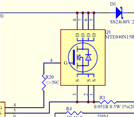
We are using the LM3431 to drive the TFT backlight, and the backlight structure consists of 11 sets in series with 4 LEDs in parallel in each set, with a current of 100mA for each set.

The input voltage is 24V, but the measured output voltage is 37.5V, and the current is 0mA. Can you please help me determine if there is a design error in the circuit?   

   3482.lm3431-circuit.pdf      

  • Hi Brian,

    Please give us some time to get back to you on this.

    Thanks Tuan

  • Brian,

    1.  Please number the pins on the left hand side of the LM3431.  I just want to check and verify correct pin numbers.

    2. What voltage is powering OP1 OP-AMP?  Is it VCC of the LM3231.  It's not labeled on the schematic.

    3.  What is the voltage on LED_OFF?

    4.  What is the voltage on DIM (Pin 27) of the LM3431?

    5.  What is the voltage on base of Q5.

    Thanks Tuan

  • Hi Tuan,

    Here are the voltage readings for each point, as requested in your message.

    Please help me confirm which part of the circuit design has a problem.

    Thanks  Brian

    LM3431-SCH-20231109.pdf

  • Hi Tuan

    Update our circuit as attach for you reference,  we use the analog mode for dimming at this moment  but we will use digital mode for future designed

    Thanks for help

    LM3431 test report.pdf

    LM3431-SCH-20231109(NEW).pdf

  • Hi Tuan

    Regarding R20, it has already been shorted in the PCB layout, so there is no resistor on it. Please take note, and thanks!

    Brian

  • Brian,

    Please give us some time to review this.

    Thanks Tuan

  • Brian,

    1. Did you use the Mathcad file on the TI website to do you design?  

    2. What is the LED part number?  I like to verify the output voltage

    3. Can we have a scope capture of SS/SH with LED_OFF initially at 0V then pull it up to 5V...I am trying to see initial condition with soft-start here.  Trigger on LED_OFF on rising edge on CH1.    CH2: SS/SH       CH3: LG     CH4:  VLEDA.  

    What application is this for and is it automotive related?  The reason I ask is that this is an older part and it might be better to use a new part with better features and ease of use.

    Thanks Tuan

  • Hi Tuan

    Here is our designed value from Mathcad file

    LM3431-mcdx.rar

    The LED_OFF  vs LG    and  LED_OFF vs  VLEDA  is in below

     LM3431 test report-1.pdf

    Here is video for LED_OFF vs SS/SH 


  • Hi Tuan,

    May I know your time zone? This case has become urgent, and I need to work more efficiently. This is an automotive application for a 12.3-inch backlight driver. We need this solution because the previous backlight solution had heat-related issues.

  • Brian,

    I need the scope capture of LED_OFF with SS/SH capture and not a video of it.  I am looking for something like figure 15 of the data sheet to see the ramp up of SS/SH.

    I am in Colorado so it Mountain Time in the US.  I am currently on vacation and will not return until later in the week.

    You mentioned there is heat related issue.  Is it the LM3431 that is heating up or is it the external FET that is heating up?

    Thanks Tuan

  • Brian,

    I also asked for the LED part number so I can verify the LED voltage.  

    Thanks Tuan

  • Hello Tuan

    The issue with LM3431 has been resolved. I find that in Digital mode, the DIM pin cannot be directly connected to Vcc(5V); there must be a time delay for it to start up properly. In analog mode, the voltage on the DIM pin should not exceed 2.7V. After providing the correct signal to DIM, the LM3431 is now functioning correctly. Thank you for your assistance, and  wish you have nice vacation!

  • Brian,

    I am glad that you have resolved the issue.

    Thanks Tuan