This thread has been locked.

If you have a related question, please click the "Ask a related question" button in the top right corner. The newly created question will be automatically linked to this question.

LM5023: How to Calculation the Current of AUX windings?

Part Number: LM5023

Hi TI’s Experts:

Here is a Webench Design link of LM5023: webench.ti.com/.../SDP.cgi

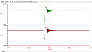
The circuit working conditions are described as follows: Input normal voltage is 58V;Output Voltage is 125V and maximum output Current is 0.3A. The recommended transformer turns ratio is Np:Ns:Naux=24:60:6, and According to my personal deduction, the peak current on the primary side is about 4 amps.


Q1:How to Calculate the peak current of AUX windings? in my opinion: At the beginning of OFF Time, the current of AUX windings is equal to Np*Ipri(peak)/Naux, which is about 16 amps. This is abnormally large.

  • If I am wrong, please point out my problem.
  • If I am right, please tell me how the energy(or Current) in OFF Time is divided between the secondary and auxiliary windings.


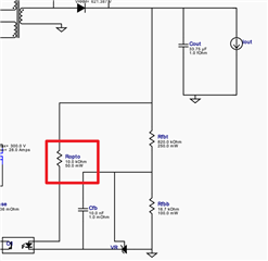
Q2: Ropto. I think the resistance's power rating Which is 50mW is too small.


Look forward to your kind reply.

  • Hi Junjie,

    Thank you for the query on the LM5023.

    1. The auxiliary winding is only going to consume current that is required to keep the controller running. So if you measure with a precision multimeter (6.5 digt one) you will see it is only going to consume close very few mA (probably less than 5mA). So the aux winding can be typically chosen for a max current of 20-30mA. This can be taken as max current. (Iamax). Iap(peak) = 2*Iamax/(1-Dmax); Iarms = Iapk*sqrt(1-Dmax)/3

    2. Optocoupler resistor seems less power rated for the output voltage mentioned. Please refer the note below for power dissipation of resistor.

    https://electronics.stackexchange.com/questions/546134/resistor-value-calculation-for-optocoupler-input

    Regards,

    Harish

  • Hi Harish:

    Thank you for your reply. I would like to discuss Q1 further.

    In the absence of circuit board, I used the TINA simulation file snvm472 to find out that the aux windings current is less than 5mA. And I had read the AN note Flyback Aux Winding OVP and UVLO Fault Sensing Design and Troubleshooting Tips Figure 3-1 to determine The consistency of auxiliary winding voltage waveform and power MOS drain waveform.

    Here is a screenshot of the transient output:

    It seems like that the aux current just only follows aux voltage.Does this mean that there is no constraint between the aux current and the primary current\secondary current?

    btw, "Iap(peak) = 2*Iamax/(1-Dmax)" is a little confusing, Please tell me what's Iap(peak) and Iamax.

    Regards,

    Junjie JI

  • Hi Junjie,

    Thank you for the reply. 

    If you just look at transformer polarity, you can get an idea when the power transfer to each winding takes place.

    So you can just think about aux winding as any other normal secondary winding (just like multi winding transformer). But remember the load here is very less around 10-20mA (which the controller requires) as I suggested earlier.

    If you consider the current shape triangular, 1/2* Ipk * (1-Dmax) = Imax

    Regards,

    Harish