Other Parts Discussed in Thread: UCC21550, UCC21551
Dear teams,
Rdt=1k is not within the range of the datasheet. Is there any other way to calculate DT at this time?
Thanks!

This thread has been locked.
If you have a related question, please click the "Ask a related question" button in the top right corner. The newly created question will be automatically linked to this question.
Dear teams,
Rdt=1k is not within the range of the datasheet. Is there any other way to calculate DT at this time?
Thanks!

As stated in datasheet section 8.4.2.2,
tDT = 8.6 × RDT + 13
For a 1k DT resistor, the deadtime will be 8.6*1+13, or about 21.6ns.
The usable deadtime range for the UCC21550 is 27-870ns, so you may have trouble getting 21.6ns accurately.
Best regards,
Sean
Hi Sean,
Then why is the usage range of RDT marked as: 1K<RDT<100K?
Thanks!

Hi Guohai,
Your highlighted text indicates that "1.7k" is the lower bound. I will try to test the deadtime with a 1k DT resistor and get back to you with the time value. It probably works fine, just the deadtime duration starts to deviate from this equation by more than the stated 7% tolerance.
What is your customer's deadtime target? Also, what is their secret to switching so quickly and efficiently? When I try to use a deadtime that low I start to have massive shoot through current. They must have a very small, low capacitance switch and an excellent gate drive circuit!
Best regards,
Sean
Hi Sean,
This will be applied at an operating frequency of 800KHz. The customer is still in the early design stage, so he wants to know the DT when RDT=1K as a reference, which is not officially used. So is this a resistor value that can be calculated?
Please allow me to ask a new question:
The working isolation voltage of UCC21550 is VDC<2121V. What will happen if it is applied in an environment exceeding this voltage value? Is it just a reduction in service life? Or will it cause damage to some parts of the IC? Please provide specific failure symptoms.
Thanks!
Hi Guohai,
I did not yet get the chance to measure the deadtime. The designer has replied to me that
"Dead-time less than 1.7k falls into the minimum dead-time region. The tolerance is extremely wide and there can be a large deviation between rising and falling dead-times. I have data for only 3 parts and RDT=1k results in between -0.6 to 5 ns of dead-time."
Best regards,
Sean
The working isolation voltage is a DC spec. Section 6.6 of the datasheet indicates that the transient voltage can be much higher (10kV in oil).

The cause of failure is arching and dielectric breakdown. Inside the device, there is a silicon dioxide dielectric that has a very high permittivity. Often the weaker link is the breakdown of the air around the device, and the isolation is limited by "creepage" and "clearance" distance. There are different standards for isolation. The UCC21551 is has a double barrier and is considered "reinforced". Here is an article to learn more: https://e2e.ti.com/blogs_/b/analogwire/posts/reinforced-isolation-when-1-is-greater-than-2?keyMatch=REINFORCED%20ISOLATION
Other types are basic and functional isolation.
Hi Sean,
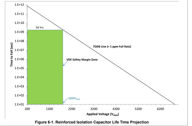
I found this picture in the datasheet. Does it mean that the increase in isolation voltage just reduces the life of the chip? For example, when Vrms=3200V, the IC can be used for about 1.E+07 seconds?
Thanks!

Hi Guohai,
Yes, that is exactly the theory behind this graph. It is based on industry recognized standards.
This graph is based on a lot of assumptions about "accelerated life". It is difficult to have an accurate measured test for 54 years! High voltage does lead to "hot carrier injection degradation" in semiconductors, which destroys the chip dielectric over time.
3200V is still well below the 5000Viso for this device. What is the application? The high voltage is likely not going to be applied across this barrier continuously, 100% of the time.
Here are some links with more information:
https://www.ti.com/lit/wp/slyy063/slyy063.pdf
https://www.ti.com/lit/an/slla353a/slla353a.pdf
Best regards,
Sean