Because of the holidays, TI E2E™ design support forum responses will be delayed from Dec. 25 through Jan. 2. Thank you for your patience.

This thread has been locked.

If you have a related question, please click the "Ask a related question" button in the top right corner. The newly created question will be automatically linked to this question.

LM337: Simulation problems with LM3337N

Part Number: LM337
Other Parts Discussed in Thread: , LM317, TPS7A39

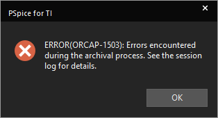
I am designing a bipolar power supply circuit using LM317lL and LM337L.  I started out using LM337N in PSPICE for TI because LM337L is not available. Ultimately I will need LM337L for layout purposes. I could download the model for LM337L but don't want to use it in the early design stages because adding it will limit me to three probes. Meanwhile I have nothing but trouble with the LM337N model. My simulations sometimes produce flatline 0V output or kilovolt spikes at the LM337 output and/or take forever to run. The outputs of the LM317 behave as expected. I attempted to attach a project, but got an error message trying to archive it. t. I looked at the session log as suggested by the attached error message, but it provided no additional information. Is there something wrong with the LM337N model?  Would it be possible to  add the LM337L to the PSPICE for TI library?
  • Hi Roger,

    I'm going to bump this to the product group as they are responsible for the model and can answer questions regarding what's going on.

    I did search for a model for the LM337L, but could find no record of a PSpice model for this device.

    Regards,

    David

  • Hey Roger,

    I'll look at this later today.  Can you please provide the session log?

    Thanks,

    Stephen

  • After opening and trying to archive the project, this is all I get in the session log (copied from the session log pane):

    INI File Location:C:\cds_spb_home\cdssetup\OrCAD_CaptureTIPSpice_Install/17.4.0/Capture.ini
    ********************************************************************************
    
    Capture Archive Project ...
    -----------------------------
    Archiving project - c:\users\rbrooks\documents\pspice\design4.opj
    Archive settings ...
    	Include library files = NO
    	Include output files = NO
    	Include referenced projects = NO
    	Create single archive = YES
    	Destination archive file = C:\Users\rbrooks\Documents\design4-2023-11-14T21-21.zip
    Creating/Replacing zip archive ...
    INFO(ORCAP-2286): Errors were encountered during archiving the project.
    

    No zipfile was created.

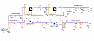
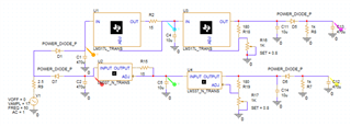
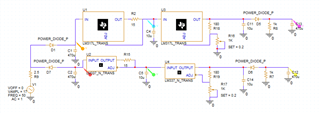
    Here is a version of the schematic which simulated successfully:

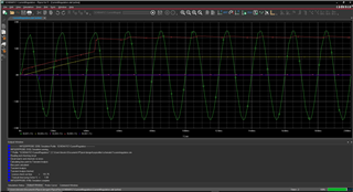
    and here is the simulation:

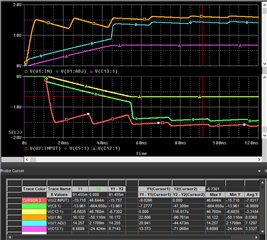
    However, tinkering with the "SET" points of the pots R12 & R13 can cause the simulation to take all night to finish, produce spikes at the output of U2 or give a flatline zero output from U4.  As long as the simulation finishes at all, the probes on the positive supply side deliver reasonable data.  Only the negative side is screwed up.

  • Can you include the library files. I was able to archive a simple project with that selected.

  • After setting the pots to 0.8 (likely irrelevant) I was able to archive the project without errors.  The attached archive was made with "include libraries" enabled, but it is the same size as one I made without that setting.

    design4-2023-11-15T05-48.zip

    However, the simulation result was a blank:

    Thanks for your help!

  • Hi Roger,

    I'm reviewing this and your other question and I'll reply back within 2 business days.

    Thanks,

    Stephen

  • Hi Roger,

    In my copy I went to add the libraries before running the simulation and Cadence notified me that the filename used an "&" which may cause problems.  I'm not sure if this was an error, but it was preventing me from saving my updates (adding the libraries).  After setting up a new simulation profile and configuring the libraries there, I also received an aborted simulation and I suspect it's due to the "&" symbol.

    I have both of your latest simulations running and converging but I needed about an hour to find the missing libraries as my version of PSpice apparently did not have them all.  I'll look further at this tomorrow.

    Thanks,

    Stephen

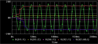
  • I am not aware of having sent any file with "&" in the name in this thread. I may well have done so in my other thread about LM337.  I did provide a link (with several "&"s) here to the page from which I downloaded a SPICE model for LM337L. I have attached here a version of the schematic whose simulation illustrates the type of problem I refer to.  The positive output looks good, but the negative output is zero, and there is an inexplicable (small) spike on the node between the two LM337s at around 12ms.

    Many thanks for  your support!

    Design4-2023-11-16T13-11.zip

  • Hey Roger,

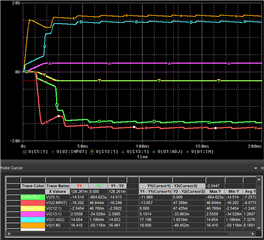
    Well it looks like the simulation is working fine for me but I downloaded all of the libraries from scratch so maybe the issue is in there.  I've attached the archived design files and if I did this correctly, you should be able to just unzip the simulation, open the project and run the simulation - and it should just work.  See if you can download this, run it, and see the same thing I show below.

    design4-2023-11-17T00-54.zip

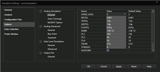
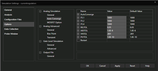
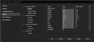
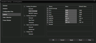
    For the record, here are my settings:

    Thanks,

    Stephen

  • I am still getting weird results, even from your version, but I now have the simulations I need for this implementation, so I am marking this resolved.

    In your archive, the library files included in my installation are provided twice, once in the root directory and once under "Additional Files". Failure to include the .lib files in the root directory leads to "Simulation aborted" (screenshot attached). 

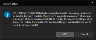
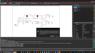
    Including the files gives me the warning that maximum three probes are supported (also attached).

    Clicking "OK" in this dialog is useless.  No matter what I try in the resulting, incomprehensible dialog for enabling and disabling probes, the warning dialog comes back. I was able to proceed by clicking "Cancel" and removing the probes at the inputs of U3 and U4 in the schematic before starting the simulation.The result looks plausible, but as you can see from my previous post in this thread, the weird results I get appear to depend on the values of passive components.

    A minor change to the resistors controlling the output voltages led again to the "imported model" warning (even though the design now includes only three probes) but the simulation still started and again delivered "Simulation aborted". Setting the pots in the attached project to 0.2 or 0.8 instead of 0.5 results in an empty simulation like the one in my post from 15 November.

    design4-2023-11-17T10-30.zip

    I have attached a new archive with all options checked, in case you want to try to reproduce this, but at this point I have what I need for this design. 

    I am still encountering problems with the design using the TPS7A39, which I will pursue in the other thread.

    Thanks again for all your help!

  • Hi Roger,

    I ran the updated file you provided and if you change the maximum step size to 100us it works. My assumption was that the simulator was having a hard time starting up the negative LDO so by forcing it simulate at higher resolution it would be more likely to get to the right answer.

    I had to download the libraries to get the previous version to simulate as I did not have them all on my computer, and if you are using PSpice for TI you would be limited to 3 probes if you were running that schematic that I provided.  I provided the library files 2x just incase there was an issue and you needed a backup copy - sorry, I should have mentioned that in my reply.

    If I change the resistors to be 0.2 instead of 0.8, I get the following results:

    Here are my settings (I didn't change anything here but I want to document this anyway in case it is helpful for you later):

    Thanks,

    Stephen

  • Many thanks Stephen, that helped a lot.  I still got a 0VDC output from the LM337 for some pot settings (e.g. 0.83), but reducing the max. step size further (to 50us) fixed that as well.

  • Because of the problems with the TPS7A39-based design, I am revisiting this.  However, PSpice for TI is complaining about foreign components, even after I deleted and replaced the components it complained about (the diodes)::

    It looks as though changing the parameters of the diode somehow changed the library components.  How can I restore the components from the default libraries and get rid of these warnings?

    P.S. Never mind: I got it working by restoring my archive from 16 November, deleting all the local libraries mentioned in my post of 17 November and applying the max. step size of 50us to the restored version.