This thread has been locked.

If you have a related question, please click the "Ask a related question" button in the top right corner. The newly created question will be automatically linked to this question.

TPS65400: QRGZTQ1

Part Number: TPS65400

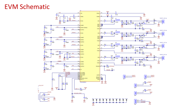
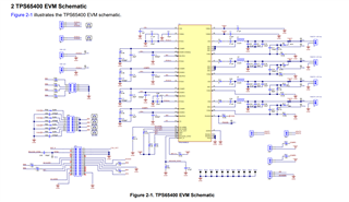
At present, we use TPS65400QRGZTQ1 chip, the input is 5V, and the output voltage is 4, respectively
1.8V@2.5A max
1.1V@2.5A max
3.3V@2.5A max
3.3V@400mA max
I am currently designing the schematic for T-Box products used in automobiles. I hope someone can guide me. Thank you

  • Hi Yaqi,

    Suggestions for you :
    1. Please pay careful attention to the datasheet and User's Guide.
    2. Please try to design according to the recommendations in the datasheet, including schematic , Layout example, and layout guidelines.
    3. After completing the first version of the design, communicate in time and I will review it .

    (Below pictures for your reference)

    Best Regards,

    Zhou

  • 0121.TPS65400.pdf
    Hello, the attachment is the schematic diagram I designed. Please check it. The input is FS56_V50. The PTA1 and PTA0 connected by I2C pull 3V3 elsewhere, so it is not reflected in this picture.
    1. Are the SS1-SS4 pins used to connect capacitors to control the power-on sequence? Can I leave these four pins floating and use programming to control the power-on sequence?
    2. How is the resistance value of the output voltage determined?
    3. I2CADDR, I2CALERT, CLK_OUTRCLOCK_SYNC, PGOOD pins, I don’t know what function they should be connected to, please guide me.
    4. What determines the size of the output current?

    There are some inaccuracies in the picture. Please correct me. Thank you.

  • Hi Yaqi,

    1.Yes. The TPS65400 has the ability to use an analog-based soft-start ramp based on external capacitors (one input for each switcher) or to use internal signals based on digital logics and DACs to perform the soft-start function.

    2.Vout = Vref x (1 +RFB1/RFB2)        Default Vref in TPS65400 is 0.8 V


    TI recommends to use a 1% tolerance resistor or better one to get higher output voltage accuracy.

    3. About how to connect I2CADDR, I2CALERT, CLK_OUTRCLOCK_SYNC, PGOOD pins.  Recommended to connect according to the EVM Schematic Example. The specific functions of these pins, it is recommended to refer to the datasheet, which has a detailed introduction.

    4. SW1, SW2 Iout: 4-A max ;SW3, SW4 Iout: 2-A max. The MOSFETs load characteristics of Buck itself determine the max value. The power consumption of the load determines the size of the output current.

    Best regards,

    Zhou

  • Hello, I have modified it according to your prompt, please check if there are any mistakes
    The function I want to achieve is: connect to MCU through IIC, control the power-on timing through MCU programming, and output the corresponding voltage. Does my circuit diagram meet the requirements?
    Thank you4578.TPS65400.pdf

  • Feedback to you later.

  • Hi Yaqi,

    1. There is a problem: the 44  -CLCK_OUT pin is not connected correctly. If you don't need an internal clock, floating is recommended.
    2. According to your connection method, there are two ways to achieve power-on timing : a. Control ENSWx through the I/O port of the MCU. b. Implemented by configuring internal sequence_order timing.

    Best regards,

    Zhou

  • hello
    1. the 44  -CLCK_OUT pin  ,I saw that the instruction manual mentioned the need to pull up, so I connected to the 3.3V power supply.
    But when I look at your reference picture, the picture on the left is incomplete. I can't see it clearly. It seems to be grounded after connecting a capacitor. Is the solution of connecting a capacitor to ground feasible? What parameters do capacitors need?

    Thank you for your guidance

  • Hi Yaqi,

    Floating is recommended.

    Best Regards,

    Zhou

  • hello
    Can you give a reference for the circuit design of a floating clock? I did not find this section in the instruction manual
    Thank you

  • Hi Yaqi,

    The 44-CLCK_OUT is the internal clock, which can sync other devices. If you use it , require pulling a resistor to VDD. If you don't use, floating is recommended.

    https://www.ti.com/lit/ug/slvuac4a/slvuac4a.pdf?ts=1700818146438&ref_url=https%253A%252F%252Fwww.ti.com%252Ftool%252FTPS65400EVM-678%253FkeyMatch%253D%2526tisearch%253Dsearch-everything%2526usecase%253Dhardware

    Best regards,

    Zhou