This thread has been locked.

If you have a related question, please click the "Ask a related question" button in the top right corner. The newly created question will be automatically linked to this question.

TPS563207S: Pspice modelling problem. Possibly newbie related.

Part Number: TPS563207S
Other Parts Discussed in Thread: TPS563207

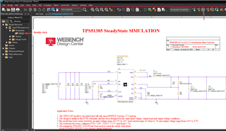
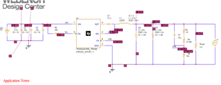
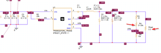
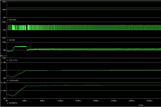
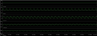
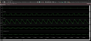
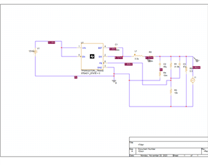
Hi . For some reason the regulator never does anything when I apply power in the simulation. I think the rest of the simulation seems ok since you can see the effect f the current source, Does anybody know why the regulator never attempts to start or do anything at all?

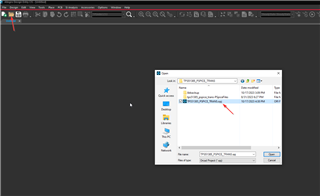
I want to upload the design for the community to see but I'm not a Pspice expert. Is uploading the .DSN file enough???

DESIGN2.DSN

Best regards,

Kevin

  • Hi Kevin

    what did your Pspice model from? I need the complete project to run.


    Have you tried the pspice model of TPS563207? It is same as 3207S and can be downloaded follow below.  

    https://www.ti.com/product/TPS563207?keyMatch=TPS563207&tisearch=search-everything&usecase=GPN-ALT

    I have downloaded and run it as well, looks good. You can also share the error messages when running your pspice model and I will check and give suggestions. thanks!

  • 7268.DESIGN2.DSN 
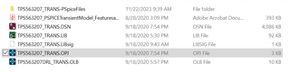
Hi Sorry will add the other files too. 

    The model came from within the PSpice TI library that was on my hard drive. Maybe it is out of date?

  • Hi Kevin,

    Xueliang will check your question and reply you by tomorrow.

  • Hi Kevin

    Please try to run the Pspice model below to check whether it is ok? thanks! 

  • Hello Xueliang.

    I haven't been able to understand how to successfully import the new model. Sorry I am not an expert with PSPice. Do you happen to have a tutorial for importing the new models? 

    Best regards,

    Kevin

  • Hi Newton

    I don't have a tutorial in hand. the following is a brief tutorial on importing the new model.

    1. Clink "Open"- find the project folder and select ".opj files".

    2. Double clink the Page1, then run it.

    Although the example is not the TPS563207 Pspice model, the import operation is the same. besides, you can search the guide on Google, which has lot of information. thanks!

  • Hi Xueliang,

    I hope you see this one more message. 

    Thank you for teaching me to import the model.

    The model is now working better. However the FB pin doesn't seem to work right. I tried changing the value of R4 to 31.55k . After making that change the output voltage stayed at 1.05V whereas my calculations suggest that should change the output voltage to around 3.3Vout.

    Is there something wrong with the FB pin in this model?

    Best regards,

    Kevin

  • I made the circuit look lie this but it still puts out 1.05V on the output which doesn't make sense...

    Best regards,

    Kevin

  • Hi Kevin

    Is it related to I1 added? I suspect that IC is in an overcurrent state, which may cause the Vout to be lower than target Vout. You can check if the Iout is more than 3A( max output current). The following is my schematic and simulation results, I only changed the feedback resistor and Rload and the Vout looks fine. If you have any questions, please upload issue waveform to analysis, thanks! 

    zoom in waveforms

  • Hi Xueliang,

    I apologize as I am still not fully understanding the correct way to use PSPice. After following the instructions above, the new model does not seem available for use in other circuits but seems to work fine in the example circuit that came with the download you pointed me to.

    The good news is I am finally getting the expected results after by modifying the sample circuit.

    I am not sure what happened yesterday but I seem to have it working fine now.

    It is funny that you mentioned current limit. I wasn't sure until I was able to finally run the simulation to completion. For a brief duration the current source is active and sinks 500mA from the output but this is in parallel with the 3R3 ohm resistor....around 1.5A out during the time when the current source is active.

    As you can see in the plot below, I am just at the parts current limit with 1.5A out. See my screen capture below. I(L1:1)max= just below 3A current limit. Also my Vout is very near my desired 3.3V.

    The voltage loop works fine. That is plenty of current for my application!

    Thanks to your guidance I now believe this circuit will be great in my application. 

    Thank you for all the help and for your patience!!!

    Best regards,

    Kevin