A related question is a question created from another question. When the related question is created, it will be automatically linked to the original question.
If you have a related question, please click the "Ask a related question" button in the top right corner. The newly created question will be automatically linked to this question.
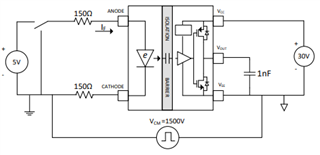
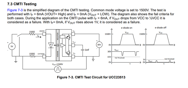
I wanted to follow up on your E2E post. In the UCC23513 datasheet we listed some of the testing conditions used. Please see below as well. Do you need guidance with the test bench set up? if so, what is your current set up?
Additionally, if you are currently working with a UCC23513EVM, I have included the user guide as well. UCC23513EVM
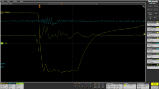
Yes it is a dedicated device. We use a Barth Model 731 3kV pulse generator and a Model 5081 Ramp Generator. It uses a high voltage coaxial cable. We charge it up to 2X the voltage required, and then close it into a matched impedance. This is also called a "pulse forming network", and the result is a relatively clean square wave pulse with a high power for a short duration. I have attached an example waveform.
As you can see, cross talk from the CMTI strike can couple into the input, and toggle the device erroneously. That is one of the reasons we recommend input capacitors and relatively low resistors between the uC and the gate driver input.
Yes, that link is exactly right. In my testing of UCC21530 and UCC21551 and similar competitor devices, the strike dragged down the input and that set the CMTI limit. I do know of a competitor device with a truly complimentary input that has 300V/ns, so I believe that this is a common issue.
The input capacitor will absorb the cross talk charge injection, and not allow the voltage to dip so rapidly. This will prevent a logic error.
The new photron device will have a 40ns minimum pulse limit, which should make it more immune to this type of CMTI noise.