This thread has been locked.

If you have a related question, please click the "Ask a related question" button in the top right corner. The newly created question will be automatically linked to this question.

LM25575: Startup glitch

Part Number: LM25575
Other Parts Discussed in Thread: LM27762, ADS114S08, LM27762EVM

Hi,

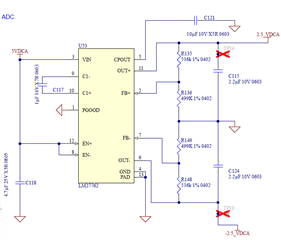
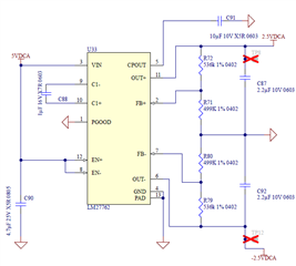
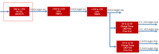
This is regarding the LM25575MHX/NOPB Step down switching regulator. Refer attached schematic snapshot and Power supply topology.

We are using this in one of our products with the following specifications:

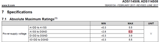
  • Input Voltage Range: 21.6Vdc to 26.4Vdc
  • Output Voltage: 15Vdc
  • Output Current: 0.5Amax


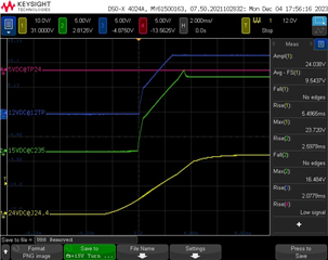
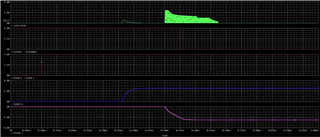
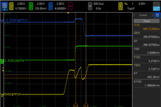
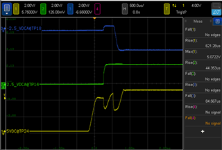
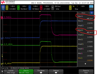
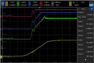
We are observing some startup glitch at the 15V output. See below green waveform.

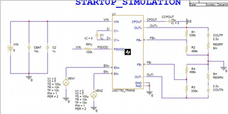
When I was trying to simulate this using Webench, the simulation is failing (Simulation not running).

Can you try to simulate or suggest what changes should be made in the design to overcome this startup glitch?

Also suggest how to make Webench simulation working.

Let me know if you need any additional details.

Appriciate if you could send me an email on Kamalnish_Arora@STERIS.com with suggested solution.


Thanks for your support.

  • Hi Kamalnish,

    Could you fill out the TI quickstart calculator? I suspect there may be insufficient COUT.

    https://www.ti.com/tool/LM2557X-557XQUICK-CALC

    Thanks,

    Andrew

  • Hi Andrew,

    I tested by adding about 30uF of COUT but it did not help much. What I noticed is that it is not LM25575 circuitry, it is about load connected on 78M05 creating this glitch. When I disconnect 78M05, I did not see the starup glitch. I also tried connecting 0.1A load (120Ohm resistor on 12V ouput) after disconnecting the 78M05 and there is no startup glitch. Refer the Power supply block diagram I shared earlier, also have a look on the circuitry used after 78M05. Two LM27762 are connected to generate +/- 2.5V for 2 different ADC chips. 

    Can you suggest what could create this startup glitch and how to rectify this?

  • Hi Kamalnish,

    During the startup of the two LM27762 devices, the peak current requirements can be higher to charge the output rails. Currently the LM27762 devices also seem to be starting during the ramp up of the 5V rail. Probably the LM25575 is getting current limited by this extra current. 

    Can you enable the LM27762 devices after the 5V has fully ramped up? You could add a RC delay between the 5V rail and EN pins of the LM27762 devices to achieve this.

    Best regards,

    Varun

  • Hi Varun, You may be right. Unfortunately I do not have a way to solder a resistor between pin 3 and 8+12 as these are connected directly to +5V plane. Do you have any other suggestion?

  • Hi Kamalnish,

    For testing, could you maybe de-solder and remove one of the LM27762s and it's 4.7uF input cap from your board? This could help reduce the total load at startup.

    Best regards,

    Varun

  • Hi Varun, Refer to my Dec 5th comment. When I removed the 78M05, it has disconnected the both LM27762 and its 4.7uF cap and we could see in below waveform there is no startup glitch. I also tested by connecting 100mA resistive load to 12V o/p just to confirm that the glitch does not apprear with the load. Do you still think removing one of the LM27762 and its cap will help? 

  • Hi Kamalnish,

    It's good that you've already verified the problem goes away when you disconnect the 78M05. 

    I think it makes sense to still verify if this really is a current limit problem in startup. Is it possible for your to probe the inductor current of the LM25575 to check if it hits current limit? You could then test if the LM27762s are working fine on your board. First by removing the loads to both LM27762s and if the problem still exists, then by disconnecting one of the LM27762s to further reduce the load.

    Does both the +ve and -ve output rails of the LM27762 regulate to the target values after startup? 

    Best regards,

    Varun

  • Can you help in simulating the LM25575, LM27762 with LM7805 using WEBENCH or LTSPICE? I am not able see LM27762 on Webench and also LM25575 simulation is not working on Webench. I want to simulate our Power supply topology 24V-->15V-->12V-->5V>+/-2.5V.  If this is not possible, at least LM27762 simulation would be preferred. Thanks

  • Hi Kamalnish,

    I have simulated the input current during startup of a single LM27762 without any load using PSPICE FOR TI.

    You can see the input current during startup of the negative rail, goes to around 1.2A. So the total input current required for starting up the 2 LM27762s and their input caps will be greater than 2.5A. If there is any load connected at the output rails of the LM27762s, then the input current is going to be even higher.

    I would suggest to use higher current parts in the power tree to supply the LM27762 or delay the turn on of the LM27762. I am not 100% sure if delaying the turn on will be enough. 

    You could also consider using a buck regulator to step down from 24V to 5V or 15V to 5V for better efficiency and thereby reduce the load current for the 24V input buck.

    Best regards,

    Varun

  • Hi Varun,

    Thanks for sharing the simulation snapshots. I also tried simulating using PSpice for TI, but not succesful yet.

    Can you please share your project file so that I can play with the component values? 

    Also, FYI, I took scope capture of +/-2.5V output from both the LM27762, see below. I am not able to understrand why -2.5V starts after about 400us of +2.5V. Is something wroing with the circuit or it is the property of LM27762. I also see that in your simulation -2.5V is started after about 140us. Do you kow what could be the reason? I am trying to understand if there is any issue with the output  of +/-2.5V rails in our design impacting the input and producing the startup glitch.

    I also wanted to know if we can add some cap on the power tree so that inrush current is supplied by caps during the current demand. Like addtion of cap on 15V or 12V or 5V o/p and after adding the delay start on LM27762 using the RC. I wanted to minimize the design change as this module is about to release.

    +15V Startup issue.zip

    Also request you to look into the attached PSPICE simulation design of 24V  to 15V of LM25575. This is throwing "ERROR(ORPSIM-15167): Undefined parameter: STEADY." I would like to simulate the complete Power Tree 24-->15-->12-->5-->+/-2.5V. 

    Appreciate you support.

    Thanks & Regards,

    Kamalnish

  • Hi Kamalnish,

    I've added the PSPICE project for the LM27762

    /cfs-file/__key/communityserver-discussions-components-files/196/LM27762_5F00_PSPICE_5F00_TRANS.zip

    I am not sure about the delayed startup of the -2.5V rail. It seems that the negative rail first goes positive before ramping down. After startup, both the rails seem to be at around 2.2V instead of 2.5V. Is this correct?

    Is there any reason why the -ve rail went positive initially at startup? There seems to be some leakage from the +2.5V to -2.5V rail at startup. Could you check if this is happening through the load? If both the +2.5V and -2.5V are used to bias an Opamp for example, there could be some leakage from the +ve to the -ve. The -2.5V starting at a positive value could also be the reason for the high inrush current. You could add a Schottky diode to the -ve rail to keep it at 0V during start up. Please see section 8.4.1 here https://www.ti.com/lit/ds/symlink/tps60402.pdf

    Adding more cap in the power tree should help supply the inrush current.

    For your question on the LM25575 PSPICE model, could you create a new post, so that the right group gets tagged to support you?

    Best regards,

    Varun

  • Hi Varun,

    Thanks for providing the PSPICE files for the LM27762. 

    Regarding your query, both rails reaches to 2.2V or 2.5V. I took another scope capture to confirm and found that both rails reaching to set value i.e +/- 2.5V. See below waveform. In my earlier waveform, it was the scale of scope capture showing around +/-2.2V.

    To overcome the -2.5V rail going positive first and then negative, I tried connecting the Schottky diode, but it did not help. Earlier, the -2.5V output was reaching to about +450mV and with Active Schottky Diode it is still about +350mV. I do not have any option to remove the load from the charge pump as I have to remove both fine chip ADC chips to verify whether the issue is from the charge pump or from the ADC circuitry. I am not sure what to do now to get rid of this. Do you think it may create any issue to ADS114S08? As of now we have not seen any failures or any issue with the ADC with this startup glitch / negative output going positive initially or with delayed start. 

    I also ordered the LM27762EVM and verified waveforms, it did not show that negative output is going positive initially at startup. Niether, the simulation shows that negative output goes positive. However, the LM27762EVM did show that negatrive output comes slightly after the positive output which is same in our case as well.

    Any suggestions from your side to further investigation?

  • Hi Varun,

    I want to give some more update on this.

    Actually, I disconnected one of the charge pump output from the load by cutting the PCB plane and noticed that the charge pump output is very clean, -2.5V rail did not show any sign of going high initially. So, no issue with the Charge Pump output. 

    I started removing the components (one by one) and still it showed some +ve voltage on the disconnected -2.5V plane.

    Howver, After removing the ADC ADS114S08, it did not show the startup overshoot. Looks like ADC has some leakage inside from +ve to -ve supply.

    Do you think I should open another post for the ADC issue? I see ADC absolute max is 0.3V, however it is reaching to +0.5V. Will there be any concern? Pelase suggest.

    Regards,

    Kamalnish

  • Hello Kamalnish,

    Thank you for the test and confirmation.

    I would suggest to create a new thread for the ADS device, since it belongs to different product line. Please refer this threat while creating a new threat for better understanding the problem.

    Thank you & Regards,

    Moheddin.