This thread has been locked.

If you have a related question, please click the "Ask a related question" button in the top right corner. The newly created question will be automatically linked to this question.

UCD3138ALLCEVM150: Cycle by cycle current control fault trigger point

Part Number: UCD3138ALLCEVM150

When I use a DPWM2 module and a comparator D to trigger a period-by-period current fault:

The setting of DPWM2 is:

In the open loop state, set the mode to normal mode, period value, and event 1, 2, 3, and 4 values to 10000, 500, 4500, 5500, and 9500

Set the blanking time A to 100(400ns) from start to end

The setting of comparator D is:

Set the comparison threshold to 100(1.95V) and connect the comparator to the DPWM2

The setting of CBC is:

CBC_ADV_CNT_EN Set this registerto 1 to enable CBC,Set the CBC PWM AB EN to 1,Set the CBC_MAX_COUNT to 4(Set the maximum number of consecutive CBC triggers to 4),Set CBC_FAULT_EN to 1 and lower DPWM if CBC_MAX_COUNT is exceeded.

I get this waveform:

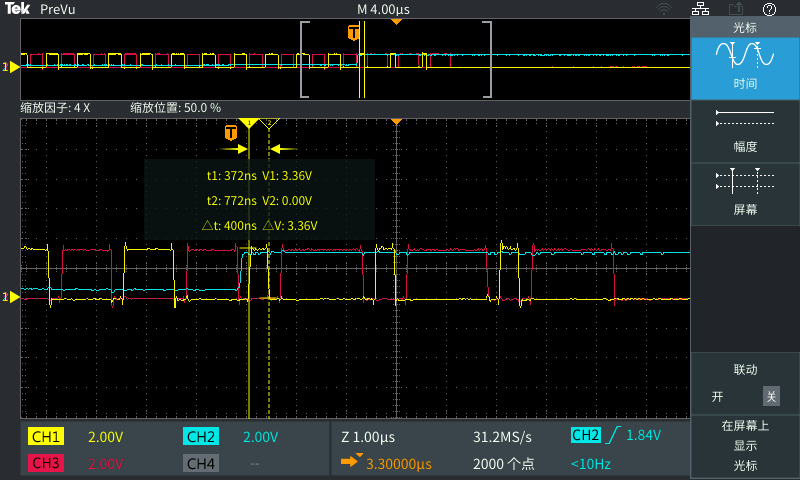
CH1 (yellow waveform) : indicates the output waveform of the DPWMA

CH2 (blue waveform) : Indicates the voltage sampled by comparator D

CH3 (red waveform) : indicates the output waveform of the DPWMB

Different trigger points have different effects on the waveform,I have a question about these waveforms:

If the falling edge of DPWMA is used as the trigger point, the DPWM wave will be lowered after 3 triggers at most, but I set 4 consecutive triggers in the Settings to lower the DPWM wave,so the trigger point for CBC is at which specific moment?

  • Hello, ML

     In terms of those topologies controlled by normal Mode PWM, the activity event for the comparator do not normally occur at the locations of scenarios 4 and 5 you mentioned.  in the practice system, the peak current is commonly occurred in the duration on-time of DPWMA. So, I am worried it is not necessary to explore the CBC behavior on normal Mode like Multiple Mode. In terms of the consecutive CBC counts, flexible configuring the register (e.g., configure 5 to obtain 4 consecutive CBC) is an option to meet your requirement. in additional, unified behavior is important and necessary. please keep feel free let me know if you find the consecutive CBC counting Inconsistent behavior between the different devices.

    thanks 

  • Hello,Bliss Zhou

      Thank you for your reply,for the continuous CBC count, can I understand that configuring 4 consecutive triggers should result in obtaining 4 consecutive CBC, where the error may be caused by hardware or measurement?

    thanks

  • ML,

    Appling a continuous high-level voltage on the comparator input may not evaluate the practice current. could you use the practice current signal to observe the CBC count behavior?

    thanks