Other Parts Discussed in Thread: LMZ10505, TPS22965-Q1

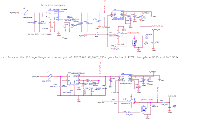
We have designed a board in which 1.5V and 3.3V is generated from SMPS LMZ10505EXTTZE/NOPB. U33 and U36 are the Load Switches. These load switches are used to protect the board. If SMPS malfunction and its Vin become Vout then board will damage (Major ICs MPC5566 and FPGA will get damage). To protect the board Load Switches are used.
In this design we are facing majorly problems from 3.3V (U36) load switch. The problems are
-
Many times we are not able to sense the 3.3V output from vout1(pin:8) and vout2(pin:9).
-
To make this load switch work, we removed CT capacitor(C344). But in some board without CT capacitor load switch work and in some board it didn’t work.
At some time when we probe CT via multimeter (after removing the capacitor) then load switch start giving the output. When we switch off and on the board then load switch stop working and if we again probe the CT then only it start work.
-
If any voltage variation happens in 3.3V then this load switch stops working (got damaged)
-
What are the failure modes of LMZ internal and external (In which Vin=Vout).
We are requesting to TI team to look the design and give us suggestion to correct the design.

