This thread has been locked.

If you have a related question, please click the "Ask a related question" button in the top right corner. The newly created question will be automatically linked to this question.

BQ76920: BQ76920 Usage, Ground and Pack-, Rsns calculation

Part Number: BQ76920

In building a Cypress PSoC project, our entire project uses a 'Gnd' in many places.

In adding a BQ76920 and LiFePO4 4 cell battery pack is presenting problems.

Namely, the TI part (BQ76920) simplified schematic indicates 'Gnd' and Pack-, but the rest of the project appears to need to be powered by Pack+ & Pack-. 

How do we go about changing the BQ76920 schematic snippet to fit into our project when 'Gnd' is used all over it, but that seems to be incorrect if 'Gnd' extends to the rest of the project?

Next, we are using an NCh MOSFET current mirror  in the charging portion of the project to limit charging to 300mA as well as fusing and a main power switch between the battery pack and the circuitry. 

There is some confusion generated by the 'Simplified Schematic' regarding where the current 'goes-ins' 'goes-outs' connections are in this topology.

Lastly, regarding the current sense resistor (Rsns) value... In using PCIFR18650-1500 cells from Zues (18650 cells limited to 4.5A max disch, 300mA nom charge), we are unsure what value should Rsns be considering OCD and SCD values unspecified by the manufacturer of the cells. We are considering 20mOhms.

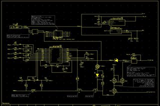
Attached is the schematic page of our project's supply. It is in flux, because of the confusions listed above.

Recommendations?

Scott DeBruyn

Dutchman Electronics LLC

  • Hi Scott,

    Namely, the TI part (BQ76920) simplified schematic indicates 'Gnd' and Pack-, but the rest of the project appears to need to be powered by Pack+ & Pack-. 

    GND on the bq76920 is going to be the ground for the AFE, but not for the rest of your system (everything past the protection FETs). Your system will need to use a separate ground connected to PACK-. The reason behind this is to prevent a current path through a common ground that leads from the system to the battery, bypassing the protection FETs. One consideration that you will need to make because of this separate ground is the I2C lines will need isolation so that the AFE and the MCU can have their own grounds. This is one of the main drawbacks of low-side FET topology, or having the FETs on the negative side of the battery.

    How do we go about changing the BQ76920 schematic snippet to fit into our project when 'Gnd' is used all over it, but that seems to be incorrect if 'Gnd' extends to the rest of the project?

    As mentioned before, the battery and the bq76920 will have their own unique Gnd that is completely separate from the Gnd used in the system. Any Gnd in the bq76920 schematic will need to be changed to a different Gnd, and then the existing system Gnd will be equivalent to PACK- on the bq76920 schematic.

    Next, we are using an NCh MOSFET current mirror  in the charging portion of the project to limit charging to 300mA as well as fusing and a main power switch between the battery pack and the circuitry. 

    There is some confusion generated by the 'Simplified Schematic' regarding where the current 'goes-ins' 'goes-outs' connections are in this topology.

    If I am understanding your question correctly, then during charging the current should "go-in" through PACK+ (on the simplified schematic) and should "go-out" from PACK- (on the simplified schematic). Discharging will be visa-versa.

    Lastly, regarding the current sense resistor (Rsns) value... In using PCIFR18650-1500 cells from Zues (18650 cells limited to 4.5A max disch, 300mA nom charge), we are unsure what value should Rsns be considering OCD and SCD values unspecified by the manufacturer of the cells. We are considering 20mOhms.

    The current protection values are usually determined by the system designer based on the system's limitations and the cells' limitations. Page 4 of the reference design document (link) provides a good example of how to pick the sense resistor value based on the chosen protection thresholds.

    Regards,

    Max Verboncoeur