This thread has been locked.

If you have a related question, please click the "Ask a related question" button in the top right corner. The newly created question will be automatically linked to this question.

BQ24295: BQ24295 Vsys not giving output

Part Number: BQ24295

On my PCB, the BQ24295 is not giving voltage on Vsys, the Vsys only has voltage when i connect the battery, and after i disconnect the battery the system oscilates and the MCU resets it self because of low voltage.

This is the schematic:

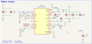
I realize that i didn´t apply the TS resistor divider (naively i didn´t add it because i thought that if i wasn´t going to use the thermistor then i wouldn´t need the resistor divider). I tryed adding the resistor divider externaly but it didn´t work either (i used a 10k/10k resistor divider and also tryed with a 5k1/10k resistor divider). I did realize though that:

Without the resistor divider on the TS pin i had a "hot thermistor fault", and everything else seems to be ok (SYS status reg gave me 10 00 1 1 0 0), but the fault reg gave the NTC_FAULT to 1.

With the resistor divider i got not faults on the register, but the system register marked 00101100, so it seems like it doesn´t detect the input voltage now.

I need that the circuitry works with and without the battery on boot, what i´m doing wrong?

thanks!!

  • Hi,

    It appears that your issue is that SYS will not come up unless a battery is present although it should if input power is available. There could be a few causes for this behavior primarily related to input power limitations and the potential SYS load.

    The TS circuit is primarily used in ensuring safe charging so it shouldn't have an effect on the SYS rail, mostly just on current through the BAT FET. Because of this I don't believe that the TS is the cause of this behavior, though it is best to look into the best TS circuit implementation for your application.

    Based on your SYS Status reg, BIT 3 seems to indicate that either VINDPM or IINDPM is active which indicates to me that DPM is limiting the amount of power we are pulling from the input. I have a few more questions for additional context:

    • Is there a load connected to SYS, and if so how much current are you expecting it to pull?
    • What kind of VIN source is being provided (i.e. what voltage)? Does it have current limitations?
    • If possible, can you please provide a waveform of VIN and SYS while battery is not present?
    • When battery is present, what voltage are you seeing on SYS and what voltage is your battery at?
    • If possible, can you please share your register configurations for the charger.

    Best Regards,

    Juan Ospina

  • Hello!, thanks you for your reply. on the questions:

    Is there a load connected to SYS, and if so how much current are you expecting it to pull?:
    Yes, i have a load connected to SYS, at peak, it should draw about 2A (obviously this is for mseconds) the expected current on the output should be less than 500mA

    What kind of VIN source is being provided (i.e. what voltage)? Does it have current limitations?:
    The Vin is a DC-DC Buck converter which outputs 5V@3A Max, it doesn´t have any current restrictions besides that max 3A

    If possible, can you please provide a waveform of VIN and SYS while battery is not present?:

    When battery is present, what voltage are you seeing on SYS and what voltage is your battery at?:
    When i meassure SYS with the battery plugged in, i see the same voltage as the battery (i have use some charged ones an another with no full charge, this is about 3.5, 3.7 and 4.2V)

    If possible, can you please share your register configurations for the charger.:
    For Sure here are all registers:
    This is when i have the battery connected and also the Vin connected
    REG0: 01011010
    REG1: 00011011
    REG2: 00011100
    REG3: 00010001
    REG4: 10110010
    REG5: 10011100
    REG6: 10010011
    REG7: 01001011
    REG8: 00101101
    REG9: 00000000

    This is when i only have the battery connected:
    REG0: 01011111
    REG1: 00011011
    REG2: 00011100
    REG3: 00010001
    REG4: 10110010
    REG5: 10011100
    REG6: 10010011
    REG7: 01001011
    REG8: 00000000
    REG9: 00000000

    Now that you asked me for the registers, i realize that after i connect the power supply the input current limit sets to 500mA, i´m not sure why, i think it has something to do with the input detection, (i have D+ and D- disconnected) how could i force it to use the 3A limt?

  • Hi Giovanni,

    As you mentioned, the 500 mA current limit can be a potential cause for this behavior. Try writing a different value to REG0 or placing a D+/D- voltage divider to program a higher limit.

    how could i force it to use the 3A limt?

    It looks like your charger is detecting an SDP source due to your D+/D- floating lines. Although you can write to the REG0 to change this configuration, in order to change it on default I recommend placing a voltage divider on your D+/D- lines so that on adapter insertion your input current limit will be higher.

    A voltage divider from VIN to D+ could provide a higher input current. These voltages indicate which voltage divider's are available for non-standard adapters:

    Best Regards,

    Juan Ospina