This thread has been locked.

If you have a related question, please click the "Ask a related question" button in the top right corner. The newly created question will be automatically linked to this question.

LM5170-Q1: Peak current limit

Part Number: LM5170-Q1
Other Parts Discussed in Thread: PMP21943, LM5170, PMP
Dear engineers:
   We apply the LM5170 to reverse polarity buck-boost and some problems occurred, the reference design is PMP21943 from TI official website.
Problem1: The inductor current peak protection deviation is extremely large.
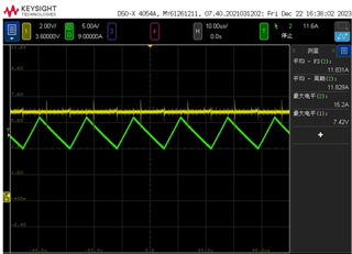
According to datasheet, we set RIPK as 57kΩ, theoretical protection point is 31.25A; but actually, it protects about 14A.
We observed the actual value of the inductor current and the sampling signal, and there were no abnormalities. Please help explain why the chip behaves like this.


The waveform is inductor current(GREEN) and Vramp(YELLOW)

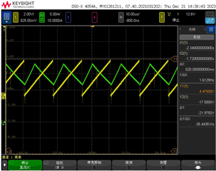
The waveform is inductor current(GREEN) and comp pin(YELLOW)

  • Hello,

    Thanks for using the e2e forum.
    You mentioned you are using the PMP21943 reference design for your LM5170 application.
    Is the schematic identical to the PMP design, or are there some modifications? In the latter case, could you share your schematic?

    Can you also provide the specs for
    - input voltage (range)
    - output voltage
    -max load conditions

    This helps us in looking deeper into the design.

    Thanks and best regards,
    Niklas

  • Hi Niklas;

    The schematic diagram is similar to that of PMP21943, but the voltage is different.

    Our design is -48V to +27V, and especially the LM5170's VIN pin is connect to PGND, not VOUT+;

    Are there any differences in the calculation methods of the inductor peak current protection point under these two wiring methods?

    the specs for
    - input voltage (range):(-48V)
    - output voltage:(+27V)
    -max load conditions:18A

    best regards,
    Stella

  • Hi Stella,

    We can see from the waveform that the peak current is around 18A.

    Please follow equation 14 in the LM5170 datasheet for best peak current limit accuracy.

    Best Regards,

    Feng Ji

  • Hello, 

    The ramp voltage always apply equation 14 of datasheet, but this is not the cause of the problem.
    As you see, the peak inductor current is around 15A, which is limited by IPK.
    But the protection point we set is 31.25A, what is the reason?
    best regards,
    Stella

  • Hi Stella,

    The two waveforms show 18A and 15A peak current respectively. What is the difference?

    If equation 14 is applied, the peak ramp voltage should be around (48V+27V)/9.6=7.8V.

    But I see the peak ramp voltage is around 5V here.

    Best Regards,

    Feng Ji

  • Hi Feng Ji:

    In fact, I have said it in previous question, our design is the same as the reference design is PMP21943 from TI official website.
    So the LM5170's VIN pin is connect to 48V, not (48V+27V);
    Would you please answer the question that how to calculate the peak inductance current limit in this wiring method?
    Are there any differences in the calculation methods of the inductor peak current protection point under these two wiring methods?


    Best Regards,

    Stella

  • Hi Stella,

    PMP21943 did not follow the stand RAMP connection because the voltage rating is higher than 95V.

    Connect VIN to (48V+27V) and follow equation 14 for constant peak current limit over the  input voltage and output voltage range.

    If you connect VIN to 48V, the peak current limit may change over the input voltage and output voltage range.

    Best Regards,

    Feng Ji

  • Hi Feng Ji:

    Would you please tell more details to help us?   

    We connect VIN to 48V, if we want the peak current limit point to be 30A, what should Ripk equal?


    Best Regards,

    Stella

  • Hi Stella,

    I don't have such equation to calculate the peak current when using a different RAMP.

    If you have to connect VIN to 48V, I would suggest to adjust the Rramp to get a peak value of (48V+27V)/9.6.

    Please keep in mind that with this method, the peak current limit may change over input and output voltage.

    Best Regards,

    Feng Ji