Other Parts Discussed in Thread: , TPS61165
Hi,
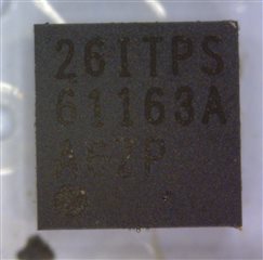
I'm having a strange behavior on a prototype with a TPS61163A.
Schematic:
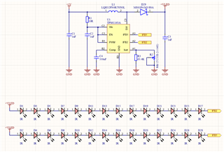
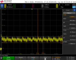
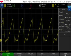
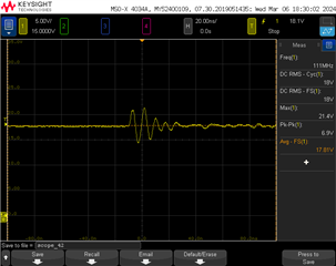
The problem is that although the datasheet says that the device can operate up to 30 mA per channel, I cannot make it supply more than 17-18 mA per channel. If I keep trimming the potentiometer (R2 mounted instead of R3 for testing purposes), the current tops at 17-18 mA in a short resistance range and then it suddenly jumps to 22 mA, and then I can further adjust it up to 28 mA, but in this 22 to 28 mA range, the TPS61163A stops working properly. For example, the open circuit detection stops working and instead tries to maintain the same total current on the remaining IFBx pin. That is if I configure the device to 28 mA and break one of the LED strips, the remaining one jumps to 56 mA.
As long as I checked, all components are well suited according to the datasheet.
This test board was manually assembled and may have a problem related to the quality of solder joints (although I didn't find any affected). Additionally, the soldering profile was somewhat aggressive (topped at 250 °C for 2 minutes).
PS: Forward voltage range for the IR LEDs is 1.2 - 1.6 V @ 20 mA.