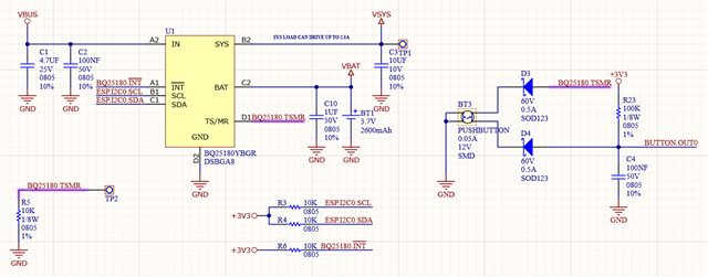
I developed a PCB using IC BQ25180.
The circuit used is in the image below. (VBUS is provide by USB)
I am communicating through I2C and set registers with the following values at board initialization:
static void BQ25180_SetDefaultConfiguration(void)
{
BQ25180_Register_VBAT_CTRL registerVBAT_CTRL;
BQ25180_Register_ICHG_CTRL registerICHG_CTRL;
BQ25180_Register_CHARGECTRL0 registerCHARGECTRL0;
BQ25180_Register_CHARGECTRL1 registerCHARGECTRL1;
BQ25180_Register_IC_CTRL registerIC_CTRL;
BQ25180_Register_TMR_ILIM registerTMR_ILIM;
BQ25180_Register_SHIP_RST registerSHIP_RST;
BQ25180_Register_SYS_REG registerSYS_REG;
BQ25180_Register_TS_CONTROL registerTS_CONTROL;
BQ25180_Register_MASK_ID registerMASK_ID;
/* VBAT_CTRL Register */
registerVBAT_CTRL.VBATREG = 0x46; //regulation in 4.2V | Battery Regulation Voltage VBATREG= 3.5V + VBATREG_CODE * 10mV
BQ25180_WriteRegister(BQ25180_REGISTER_VBAT_CTRL, (uint8_t *)®isterVBAT_CTRL, sizeof(registerVBAT_CTRL));
/* ICHG_CTRL Register */
registerICHG_CTRL.CHG_DIS = 0b0; // Battery Charging Enabled
registerICHG_CTRL.ICHG = 0x4D; // Battery Charging programmable current = 500mA
BQ25180_WriteRegister(BQ25180_REGISTER_ICHG_CTRL, (uint8_t *)®isterICHG_CTRL, sizeof(registerICHG_CTRL));
/* CHARGECTRL0 Register */
registerCHARGECTRL0.IPRECHG = 0b1; // Precharge is Term
registerCHARGECTRL0.ITERM = 0b10; // Termination current = disable
registerCHARGECTRL0.VINDPM = 0b11; // VINDPM Level Selection = Disable
registerCHARGECTRL0.THERM_REG = 0b11; // Thermal Regulation Threshold = Disable
BQ25180_WriteRegister(BQ25180_REGISTER_CHARGECTRL0, (uint8_t *)®isterCHARGECTRL0, sizeof(registerCHARGECTRL0));
/* CHARGECTRL1 Register */
registerCHARGECTRL1.IBAT_OCP = 0b11; // Battery Discharge Current Limit = Disable
registerCHARGECTRL1.BUVLO = 0b011; // Battery Undervoltage LockOut Falling Threshold = 2.8V
registerCHARGECTRL1.CHG_STATUS_INT_MASK = 0b1; // Disable Charging Status Interrupt
registerCHARGECTRL1.ILIM_INT_MASK = 0b1; // Disable ILIM Fault Interrupt
registerCHARGECTRL1.VDPM_INT_MASK = 0b1; // Disable VINDPM and VDPPM Interrupt
BQ25180_WriteRegister(BQ25180_REGISTER_CHARGECTRL1, (uint8_t *)®isterCHARGECTRL1, sizeof(registerCHARGECTRL1));
/* IC_CTRL Register */
registerIC_CTRL.TS_EN = 0b0; // TS Auto Function = Disable
registerIC_CTRL.VLOWV_SEL = 0b0; // Precharge Voltage Threshold (VLOWV) = 3V
registerIC_CTRL.VRCH_0 = 0b0; // Recharge Voltage Threshold = 100mV
registerIC_CTRL.TMRSLW_EN = 0b0; // Timer Slow = The timer is not slowed at any time
registerIC_CTRL.SAFETY_TIMER = 0b11; // Disable safety timer
registerIC_CTRL.WATCHDOG_SEL = 0b11; // Disable watchdog function
BQ25180_WriteRegister(BQ25180_REGISTER_IC_CTRL, (uint8_t *)®isterIC_CTRL, sizeof(registerIC_CTRL));
/* TMR_ILIM Register */
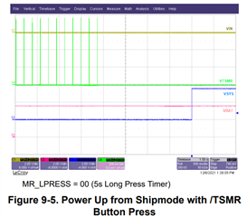
registerTMR_ILIM.MR_LPRESS = 0b00; // Push button Long Press duration timer 5s
registerTMR_ILIM.MR_RESET_VIN = 0b0; // Hardware reset condition = Reset sent when long press duration is met
registerTMR_ILIM.AUTOWAKE = 0b01; // Auto Wake Up Timer Restart = 1s
registerTMR_ILIM.ILIM = 0b101; // Input Current Limit Setting = 500mA(max.)
BQ25180_WriteRegister(BQ25180_REGISTER_TMR_ILIM, (uint8_t *)®isterTMR_ILIM, sizeof(registerTMR_ILIM));
/* SHIP_RST Register */
registerSHIP_RST.REG_RST = 0b0; // Software Reset = Do nothing
registerSHIP_RST.EN_RST_SHIP = 0b00; // Shipmode Enable and Hardware Reset = Do nothing
registerSHIP_RST.PB_LPRESS_ACTION = 0b00; // Pushbutton long press action = Do nothing
registerSHIP_RST.WAKE1_TMR = 0b00; // Wake 1 Timer Set = 300ms
registerSHIP_RST.WAKE2_TMR = 0b00; // Wake 2 Timer Set = 2s
registerSHIP_RST.EN_PUSH = 0b1;
BQ25180_WriteRegister(BQ25180_REGISTER_SHIP_RST, (uint8_t *)®isterSHIP_RST, sizeof(registerSHIP_RST));
/* SYS_REG Register */
registerSYS_REG.SYS_REG_CTRL = 0b111; // SYS Regulation Voltgage = Pass-Through (VSYS is VIN)
registerSYS_REG.SYS_MODE = 0b00; // SYS powered from VIN if present or VBAT
registerSYS_REG.WATCHDOG_15S_ENABLE = 0b00; // I2C Watchdog = Disable
registerSYS_REG.VDPPM_DIS = 0b0; // Enable VDPPM
BQ25180_WriteRegister(BQ25180_REGISTER_SYS_REG, (uint8_t *)®isterSYS_REG, sizeof(registerSYS_REG));
/* TS_CONTROL Register */
registerTS_CONTROL.TS_HOT = 0b00; // TS Hot threshold register = 60°C
registerTS_CONTROL.TS_COLD = 0b00; // TS Cold threshold register = 0°C
registerTS_CONTROL.TS_WARM = 0b1; // TS Warm threshold = Disabled
registerTS_CONTROL.TS_COOL = 0b1; // TS Cool threshold register = Disabled
registerTS_CONTROL.TS_ICHG = 0b0; // Fast charge current when decreased by TS function = 0.5*ICHG
registerTS_CONTROL.TS_VRCG = 0b0; // Reduced target battery voltage during Warm = VBATREG -100mV
BQ25180_WriteRegister(BQ25180_REGISTER_TS_CONTROL, (uint8_t *)®isterTS_CONTROL, sizeof(registerTS_CONTROL));
/* MASK_ID Register */
registerMASK_ID.TS_INT_MASK = 0b1; // Mask TS Interrupt
registerMASK_ID.TREG_INT_MASK = 0b1; // Mask TREG Interrupt
registerMASK_ID.BAT_INT_MASK = 0b1; // Mask BOCP and BUVLO Interrupt
registerMASK_ID.PG_INT_MASK = 0b1; // Mask PG and VINOVP Interrupt
BQ25180_WriteRegister(BQ25180_REGISTER_MASK_ID, (uint8_t *)®isterMASK_ID, sizeof(registerMASK_ID));
ESP_LOGI(TAG, "Registers defined to custom configuration!");
}
At a certain point, I call the following function to put it in SHIPMODE
void BQ25180_SetShipMode(bool enable) {
BQ25180_Register_SHIP_RST registerSHIP_RST;
if(true == enable) {
registerSHIP_RST.PB_LPRESS_ACTION = 0b01; // Pushbutton long press action = Hardware Reset
registerSHIP_RST.EN_RST_SHIP = 0b10; // Enable shipmode with wake on button press or adapter insert
ESP_LOGW(TAG, "Ship mode will be set to ON!");
}
else {
registerSHIP_RST.PB_LPRESS_ACTION = 0b00; // Pushbutton long press action = Do nothing
registerSHIP_RST.EN_RST_SHIP = 0b00; // Do nothing
ESP_LOGW(TAG, "Ship mode will be set to OFF!");
}
BQ25180_WriteRegister(BQ25180_REGISTER_SHIP_RST, (uint8_t *)®isterSHIP_RST, sizeof(registerSHIP_RST));
}
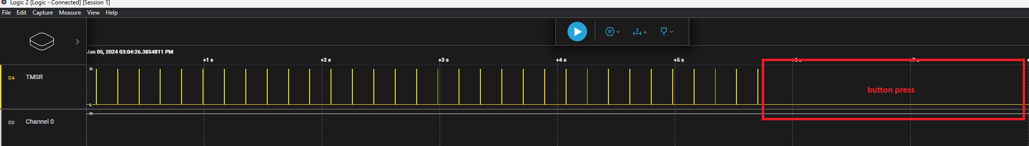
The chip behaves as expected when entering SHIPMODE, the output voltage is cut and consumption remains as expected, HOWEVER, I can only exit SHIPMODE mode when I connect VIN.
Could you tell me what I'm doing wrong? I am completely at your disposal for any questions or necessary tests.
I try change the value of registerSHIP_RST.EN_PUSH but without sucess.