


Other Parts Discussed in Thread: TPS92518, , LEDSPIMCUEVM-879
I am reaching out to you today to seek your assistance in the development of a product utilizing a custom-made electronic board based on an STM32 microcontroller, along with your LED driver (TPS92518).
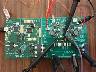
My team and I recently acquired both development boards, LEDSPIMCUEVM-879 and TPS92518EVM-878, and have not attained the desired outcomes.
Here is our testing procedure:
- Installation of the software provided with the development board (as per support's recommendation) on a Windows 10 computer.
- Preparation of the development board (MCU + Driver) under a 48V power supply with oscilloscope monitoring.
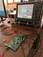
- Connection between the TI software and the development board --> Successful connection with visible SPI frame on the oscilloscope.
- Attached is the configuration of our system calculated using your software.

- Definition of values in the driver registers (decimal):
* CONTROL_value = 31, CONTROL_adress = 0,
* THERM_WARN_LMT_value = 159, THERM_WARN_LMT_adress = 2,
* LED1_PKTH_DAC_value = 23, LED1_PKTH_DAC_adress = 3,
* LED2_PKTH_DAC_value = 23, LED2_PKTH_DAC_adress = 4,
* LED1_TOFF_DAC_value = 28, LED1_TOFF_DAC_adress = 5,
* LED2_TOFF_DAC_value = 28, LED2_TOFF_DAC_adress = 6,
* LED1_MAXOFF_DAC_value = 30, LED1_MAXOFF_DAC_adress = 7,
* LED2_MAXOFF_DAC_value = 30, LED2_MAXOFF_DAC_adress = 8,
Upon activating both channels of the driver on the software, nothing happens. We have attempted to adjust parameters randomly available on the software, and at certain non-reproducible moments, channel 2 and then channel 1 lit up for a few seconds.
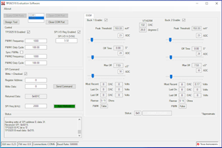
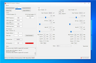 Only channel 2 was lit up and we can see the "pwm" box set as "true"
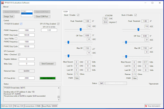
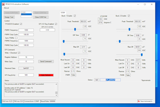 Only channel 1 was lit up and we can see the "pwm" box set as "false"
There are screenshots of these instances when the LEDs illuminated. These elements should provide a detailed insight into our current configuration and the issues we are facing. We believe that a more in-depth expertise from your team could be beneficial for overcoming the current situation.
If possible, could you please guide us on corrective steps we could implement or direct us to additional resources that might be helpful?
We appreciate in advance the attention you will give to our request. We are eager to progress in our project with your valuable assistance.
Best regards
Mr Levesque, Embedded engineer in Obsta Company, France.
