This thread has been locked.

If you have a related question, please click the "Ask a related question" button in the top right corner. The newly created question will be automatically linked to this question.

UCC28951: UCC28951 sync rectifier problem

Part Number: UCC28951
Other Parts Discussed in Thread: UCC28950, UCC28950EVM-442

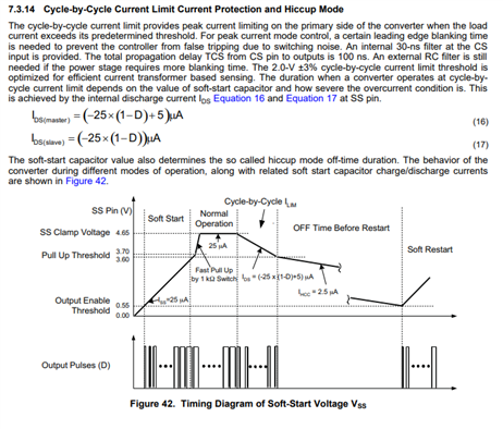
I am using the UCC28951 PWM IC in  a power supply with a 24 Volt input and a 5 volt output.  When I enable the synchronous rectifiers, the timing on the UCC28951 becomes unstable.  It causes the primary to go into overcurrent hiccup mode.  I have checked the phasing between the primary and the secondary sync rectifiers.  The phasing is correct.  I have included the schematic.   I am not using adaptive delay.  FIB_power_supply.pdf

  • Hello,

    I am reviewing your inquiry and will get back to you shortly.

    Regards,

  • Hello,

    I reviewed your schematic and it looks like your E and F SR FETs are not driven with the right outputs of the UCC28951.

    You can use the UCC28950EVM-442 schematic as a reference.  Please note that the UCC28950 and UCC28951 are pin for pin compatible and would use the same schematic.  The following link with bring you to the UCC28950EVM-442 user's guide which contains teh UCC28950EVM-442 schematic.

    https://www.ti.com/lit/ug/sluu421a/sluu421a.pdf

    Regards,

  • Hi Mike,

    Thank you for your help.  I have used the UCC28950 in the past and I am familiar with the UCC28950EVM-442 schematic

    The sync rectifiers are driven by UCC28951 E and F outputs (pins 18 and 17 respectively) thru resistors R22 and R30 to an isolator UCC2150ADWR (U5).  The output of U5 drives the two sync FETS Q8 and Q5.  The reference design does not use the UCC2150ADWR but we are driving the sync rectifiers the same way from the UCC28951.  

    I have used both the UCC28951 and the UCC2150ADWR in this configuration in the past and has worked with out this problem.  The big difference between these designs is the layout. 

  • Hello,

    Your inquiry is under review and I will get back to you shortly.

    Regards,

  • Hello,

    I think you erratic behavior may be because you are hitting the over current hiccup mode protection. 

    You can verify this by studying the Comp, CS, Transformer Input Voltage and you might as well look at Out E and Out F since you have an extra probe.  If the SS voltage is cycling during this most likely you are hitting over current hiccup mode.

    I would study these signals when the SRs are off steady state and when you turn them on.  This information will help you determine what is causing the erratic behavior.

    Regards,