This thread has been locked.

If you have a related question, please click the "Ask a related question" button in the top right corner. The newly created question will be automatically linked to this question.

BQ25730: Charging solution

Part Number: BQ25730
Other Parts Discussed in Thread: BQ25720, BQ25731, BQ25750

Hi,

In our project we need to use a charging solution,please help provide a suggested IC

First, I will list some of our requirements for charging equipment.

A DC adapter will be used as the input power on our system, the specification is 9 volts/10 amps.

Our battery packs use Li-Polymer cells with specifications from 6 to 8.4 volts/10 amps, configured as 2S (2 batteries in series).

There are three different applications in the charging system according to customer needs.

  • Case 1  (cost-saving version): Using a DC adapter as the input power supply and removing the Ll-Polymer battery. The output power specification requires is ~9V/10A.(keep the charging IC on the PCBA).
  • Case 2: Using a Ll-Polymer battery as the input power supply and removing the DC transformer, , The output power specification requires  is ~6 to 8.4 volts/10 amps.
  • Case 3: The DC adapter is used as the input power, and the Ll-Polymer battery is retained. The output power specification requires  is ~9 volts/7 amps, and 3 amps are provided to charge the battery.

Our questions : 

  • Can you help confirm that BQ25720 or BQ25730 meets our needs? Or have other suggested ICs.
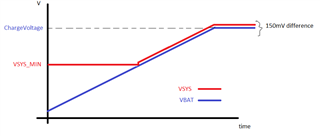
  • Can you help confirm that BQ25720 or BQ25730 have dynamically adjust the VSYS setting value? (For example: VIN=9V,VSYS=5V or 6V or 7V…)
  • What is the difference between BQ25720 and BQ25730?
  • Hi Steve,

    Both BQ25720 and BQ25730 meets you needs specified in cases 1 to 3. Both of these chargers support system power from adapter without battery, supplement system power with battery and provide system power with battery only.

    The main difference is BQ25720 supports higher switching frequency than BQ25730. However, BQ25730 support up to 5S battery while BQ25720 support up to 4S battery. BQ25720 use SMBus for host control while BQ25730 use I2C for host control. With these differences, the two charge controllers are functionally similar and behaves in similar way.

    About the dynamically adjusting VSYS, These charge controllers can only adjust VSYS_MIN voltage which is the system output voltage when the battery is below VSYS_MIN voltage. You can adjust it your desired value. As long as battery is below VSYS_MIN, the charge controller will regulate the voltage at VSYS_MIN. When the battery voltage is above VSYS_MIN, system voltage will rise above tracking the battery voltage.

    Best Regards,

    Munir

  • Hi MD,

    It looks like good news.

    We plan to start drawing the circuit, but there are still some questions that we need your help to clarify.

    • We hope to use the same design for Case 1 ~ 3. Could you please give me some suggestions on hardware and software design? (Example: How to set CELL_BATPRESZ?).

    • In Case 1, because the battery was removed,is VSYS the set value for VSYS_MIN?

      Could you please confirm how IBAT and IIN needs to be set?

      (Example: DC adapter VIN=9 volts/10 amps; VSYS=VSYS_MIN=9 volts/10 amps?)

    • In Case3, we plan VSYS to be equal to 9V/7A, VBAT to be equal to 6 to 8.4V (battery is 2S), and IBAT to be equal to 3 amps.

                I don't know the instructions on the specification sheet. Is it possible to satisfy VSYS equal to 9V/7A and use 3 amps of current to charge the

                battery at  the same time? If not, could you please provide other suggestions?

    • Could you provide the reference design of BQ25720 and BQ25730 in ORCAD format?
    • About dynamic adjustment of VSYS. Could you please confirm whether IBAT fast charging can be satisfied when VSY MIN is set higher or lower than VBAT?

               (Like Case 3;

               VSYS_ MIN=VSYS=9 V; VBAT=6~8.4V; IBAT setting 3A.

               VSYS_ MIN=VSYS=6.6 V; VBAT=6~8.4V; IBAT setting 3A)

    Thanks.

  • Hi Steve,

    1. The CELL_BATPRESZ voltage depends on your battery. Please refer to datasheet section 9.3.7. Additionally, there is a schematic checklist in this link here. 

    2. VSYS is regulated at VSYS_MIN as long as battery is below VSYS_MIN. Refer to datasheet section 9.4.1.1. 

    IBAT can be programmed in register 03/02h. Refer to datasheet section 9.6.2.

    IIN can be programmed using resistor on ILIM_HIZ pin and IIN_HOST register 0F/0Eh. Refer to datasheet section 9.3.6 and table 9-1 for input current limit.

    I notice that in your example the input power and output power is exactly the same, 90W. There is always some efficiency loss, so you will be receiving less than 10A charge current.

    3. That table you mentioned is when the charger is operating in LDO mode or when the charging is in pre-charge phase. Once the battery voltage is high enough for the charging to be in fast charge phase, full charge current of 3A will be supplied.

    4. for the reference design please send me a friendship request on e2e. 

    5. For fast charging to happen battery voltage should be higher than  VSYS_MIN. Otherwise the BATFET will be in LDO mode and charge current will be clamped as indicated by the table screenshot you posted. 

    VSYS_ MIN=VSYS=9 V; VBAT=6~8.4V; IBAT setting 3A ===> 3A charge current will never be applied

    VSYS_ MIN=VSYS=6.6 V; VBAT=6~8.4V; IBAT setting 3A) ===? 3A charge current will be applied when VBAT>6.6V

    Best Regards,

    Munir

  • Hi MD,

    1. Due to customer needs, it may happen that the 2S battery is used or the battery is removed.

    Could we always set CELL_BATPRESZ to 2S? Is there any problem with removing the battery in this condition?

    If it can't be set up like this, any suggestions?

    2. Is there any data available for us to refer to regarding the voltage conversion efficiency of 25720 and 25730?

    3. VSYS_ MIN=VSYS=9 V; VBAT=6~8.4V; IBAT setting 3A ===> 3A charge current will never be applied

    • Steve :  Is there another charging IC that can meet this requirement?

    VSYS_ MIN=VSYS=6.6 V; VBAT=6~8.4V; IBAT setting 3A) ===? 3A charge current will be applied when VBAT>6.6V

    • Steve :  Charge under this condition.

             When VSYS_MIN > VBAT;VSYS = VSYS_MIN。

             When VSYS_MIN < VBAT ; VSYS will be dynamically adjusted with VBAT (VSYS=VBAT). Is this correct?

    4. May I ask about the relationship between Charger voltage and VSYS_Min and VSYS?

    Under what conditions is VSYS=VSYS MIN used?

    Under what conditions is VSYS=CHARGER VOLTAGE used?

    Thanks.

  • Hi Steve,

    1. If you plan to use different battery configuration for example 2S or 3S then it is best to set the CELL_BATPRESZ to the highest battery setting (in this case 3S) and adjust ChargeVoltage register to appropriate value when 2S battery is used. If battery is removed then CELL_BATPRESZ should be pulled down to ground to indicated battery removal to the charger.

    2. The efficiency plots are included in the datasheet.

    3. You can disable the LDO mode in register 00h to disable the pre-charge current mode. However, the charge current may still be limited at low battery voltage depending on the battery pack internal resistor. You can also look at BQ25731.

    your understanding is correct on VSYS being dynamically adjusted with VBAT (VSYS=VBAT). However, it should be noted that VSYS is not exactly equal to VBAT but nearly equal. VSYS sits about 150mV above VBAT.

    4. Refer to the following plot.

    Best Regards,

    Munir

  • Hi MD,

    1.How should we set the battery configuration for customers to use 2S or remove the battery?

    Plan to set CELL_BATPRESZ to 2S when the battery is removed.

    At this time, VSYS_MIN=6.6V, CHARGER VOLTAGE=8.4V. Will this cause any problems?

    If you want VSYS to always be 9V when the battery is not connected, how to set VSYS_MIN and CHARGER VOLTAGE?

    2.Could you please tell me where it is in the specification sheet?

    (For example 1:Adapter Vin=9.0V;VSYS=8.4V).

    (For example 2:Adapter Vin=9.0V;VSYS=9.0V).

    3.You mean to disable LDO mode (as shown below) and fast charging can also be done under the condition of VSYS_MIN>VBAT, right?

    (Example: VSYS_MIN=9V, VBAT=6~8.4V, Disable LDO MODE), under this condition VSYS is always VSYS_MIN, right?

    We have found other charging ICs. Does TI have a similar solution?

    • Use I2C or SMBUS to transmit information.
    • Without a battery, VSYSTEM is supplied directly from VIN.
    • With a adapter and battery, VSYSTEM is directly provided by VIN; VBAT is charged by the SW Pin of the Charger IC.
    • In battery-only conditions, VSYSTEM is provided by VBAT

    4.OK.

  • Hi Steve,

    1. It is best to pull CELL_BATPRESZ  to ground when battery is removed in order to let the charger adjust its operation.

    2. Page 21 shows efficiency plot with VOUT=8.4V, 12.6V for VIN=5V, 9V. You can make a educated guess on the efficiency based on these data.

    3. Yes disabling LDO mode allows fast charging at VBAT < VSYS_MIN.

    You can take a look at BQ25750 and see if that meet your needs.

    Best Regards,

    Munir

  • Hi MD,

    1.We plan to refer to the design of the development board and add Q12 to determine whether the CELL_BATP setting is a 2S battery or to remove the battery.

    Are there any problems with this solution? (CELL_CTRL=HI, CELL_BATP=Remove battery; CELL_CTRL=LO, CELL_BATP=2S battery).

    Could we know whether BQ25720 or 25730 has the function of detecting battery removal?

    We want to provide this information to an external controller (for example: MCU) through I2C, and the MCU controls the CELL CTRL PIN.

    2.OK.

    3.BQ25750 looks good, but it's a bit expensive. Could you recommend other cheaper charging ICs?

  • Hi Steve,

    1. Q12 looks good. The EVM also uses the same solution.

    You can use STAT_Battery_Removal in register 22h for detecting battery removal.

    3. We do not have any other solution at this moment.

    Best Regards,

    Munir

  • Hi MD,

    1.How to detect STAT_Battery_Removal and STAT_Adapter_Removal?

    Is it through the voltage detection of VSRN and VACP?

    Thanks.

  • Hi Steve,

    As I said earlier, STAT_Battery_Removal in register 22h can indicate battery removal. In order to read that status you need to set PROCHOT option PP_BATPRES in register 38h. When battery is removed and CELL_BATPRESSZ is 0V, STAT_Battery_Removal will be read as 1. Once it has been read, it will be automatically reset to zero.

    For adapter simply look at the charge status register.

    Best Regards,

    Munir