This thread has been locked.

If you have a related question, please click the "Ask a related question" button in the top right corner. The newly created question will be automatically linked to this question.

LM5158-Q1: Inquiries about characteristics.

Part Number: LM5158-Q1
Other Parts Discussed in Thread: LM5158

Hi

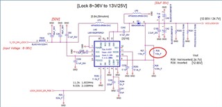
The SEPIC circuit was constructed and designed with the following specifications.

However, problems arise under the following conditions.

-SPEC-

INPUT: 8~36Vdc

Output: 24.7V or 12.85V (Set the voltage depending on whether the R38 resistor is inserted or not.)

-Question-

1. If the output voltage is set to 24.7v without inserting R38, noise occurs at an input voltage of 26V or higher and heat is generated severely.

2.If the output voltage is set to 12.85v, the input voltage will operate up to 36v without any problems

3.Why are the above two problems happening? Is there a solution?
Please review the circuit diagram below.
Thanks

  • Hi David,

    Thanks for using the e2e forum.

    When designer power stage with adjustable output voltage, it comes with a bigger challenge in finding a loop compensation that works stable for all possible output conditions.
    Based on your description, it might be possible that the design runs stable for output voltage of 12.85V, but runs unstable at 24.4V which causes oscillation, higher losses or worse thermal performance.

    To check if this is the case, feel free to use our LM5158 quickstart calculation tool and check all values both for 12V and 24V output settings.
    https://www.ti.com/tool/download/SNVR512

    If you do not find any mismatch between the calculator and your design values, feel free to send me the filled calculator and I will double check from my side as well.

    Thanks and best regards,
    Niklas

  • Hi Niklas

    I will send you the design contents by dividing the output voltages of 12v and 24v.
    Please review it.

    sLM5158_Excel_Quickstart_Calculator_for_SEPIC-12V-GQT.xlsx

    LM5158_Excel_Quickstart_Calculator_for_SEPIC-24V-GQT.xlsx

    Thanks

  • Hi David,

    Thanks for filling in the quickstart calculators.

    Have the two tests been performed under load?
    Based on the calculator, the maximum load requirements might be to large for the device to handle in worst case conditions (minimum Vin). In this case, overcurrent protection would be triggered.
    As per your description, the noise occurs at higher Vins, where the primary side current is lower, so this should not be the source for this issue.

    The switch note voltage ratings are higher for larger Vout settings, as the SW votlage is the sum of Vin & Vout in SEPIC topology, but even at Vin 36V, this should still be within spec of the 85V max rating of LM5158.

    The loop stability is worse for the 24V settings as expected, but the system should still be stable.

    Would it be possible to perform a waveform measurement of the SW signal when it starts to oscillate at higher Vin values?

    Thanks and best regards,
    Niklas