Hi
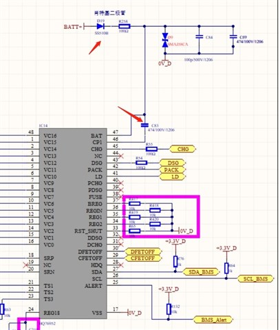
The customer design with BQ76952, when the battery rated voltage is 12V (4 cells) and 24V (8 cells), the charge and discharge drive level is only 10.35V, and the measured voltage on the bootstrap capacitor is 10.6V.
The bootstrap capacitor is 470nF, the diode D19 is a Schottky diode, and the measured voltage drop is 0.17V.
When the battery rated voltage is 48V (15 cells), the voltage on the bootstrap capacitor is 11.1V, and the charge and discharge drive level can reach 10.8V.
The queries as below:
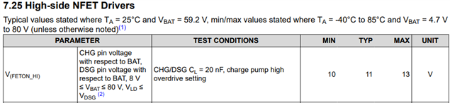
1, What is the nominal charge and discharge drive current, and the drive ability?
2, Why is the bootstrap voltage of the 48V platform relatively high at 11.1V, while the driving voltages of 12V and 48V are relatively low at 10.6V? Is this a characteristic of the chip itself or is it related to the parameter design of the driving circuit?
3, On the 12V and 24V platforms, try adjusting the bootstrap capacitor to 1uF and 1.5uF. The level on the bootstrap capacitor remains unchanged at 10.6V. How can I adjust the parameters or adjust the circuit to increase the driving voltage?