This thread has been locked.

If you have a related question, please click the "Ask a related question" button in the top right corner. The newly created question will be automatically linked to this question.

TPS546C20A: Low-Frequency Oscillation and Low-Frequency Flat Loop Gain

Part Number: TPS546C20A
Other Parts Discussed in Thread: TPS546C23,

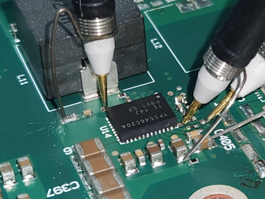
I am facing two issues with TPS546C20A on a single phase design.

Input: 12V

Output: 0.845V 30A 

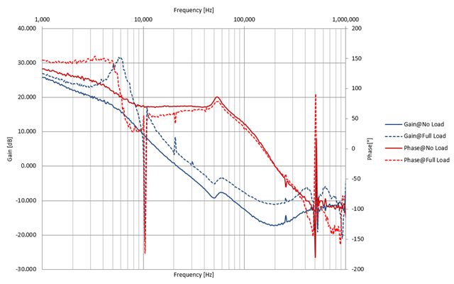
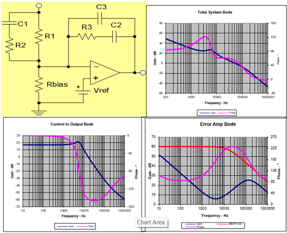
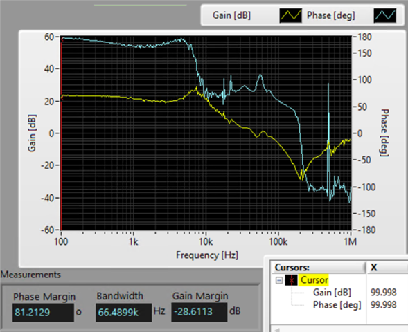
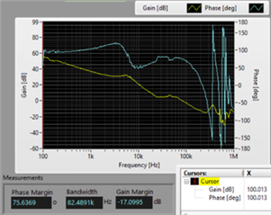
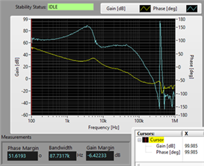
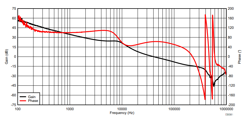
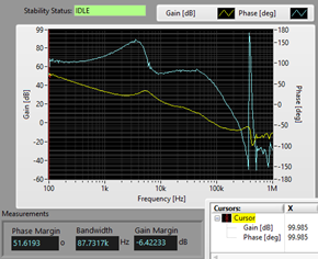
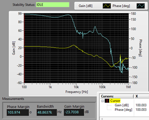
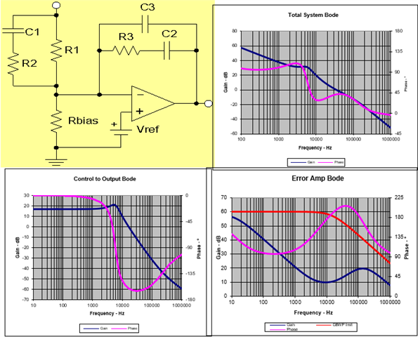
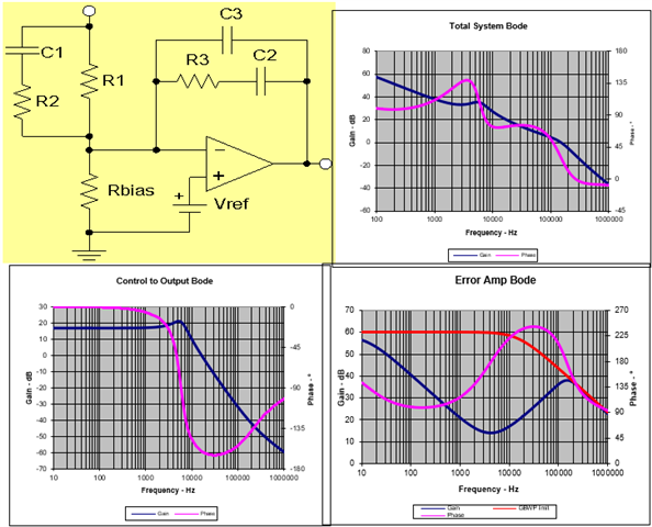
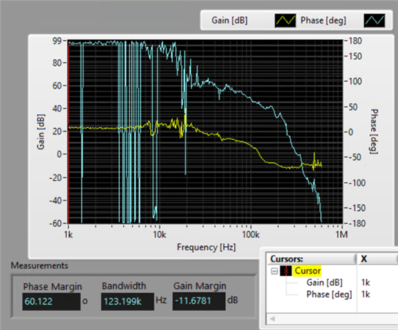
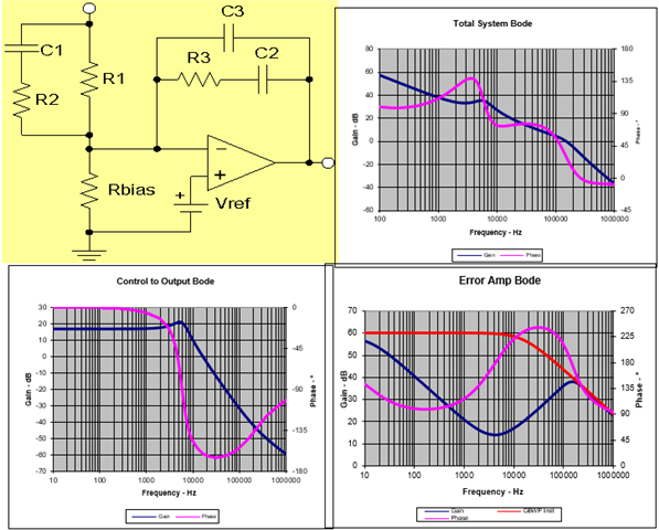
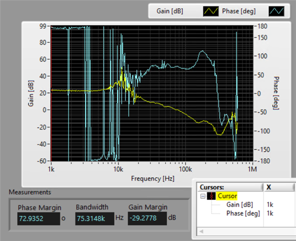
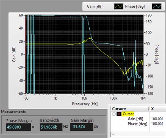
Issue 1: On the measured loop gain, at the low frequency region (1kHz to 4kHz, see Case 4 below for 100Hz to 4kHz), there is no -20dB/decade slope, unlike the designed loop gain bode plot. Type-3 Op-Amp compensator should have a pole at origin that sets a high low-frequency gain and initial -20dB/decade roll-off. What could contribute to a zero at low-frequency to cancel this origin-pole?

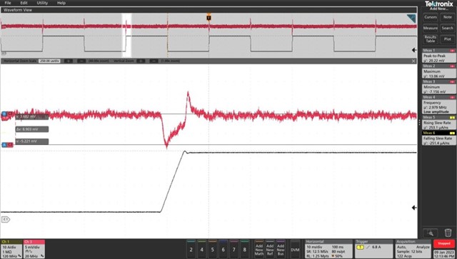
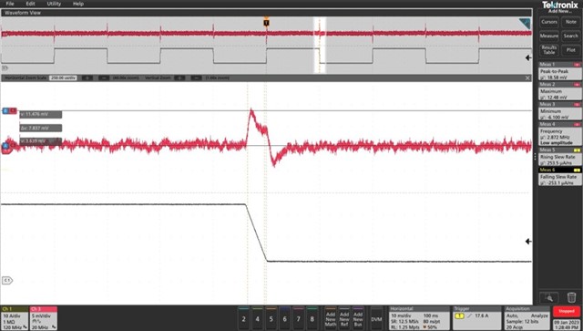
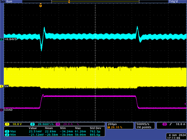
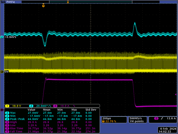
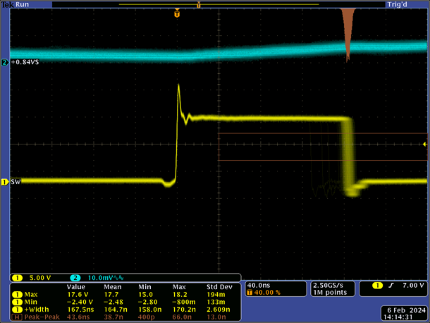
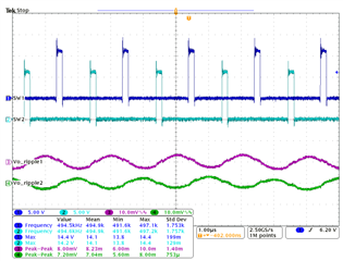
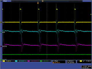
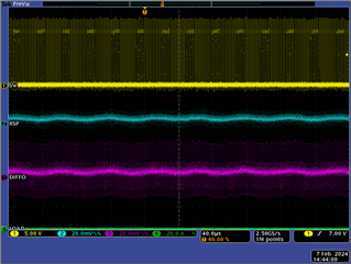
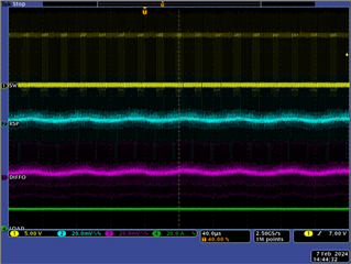
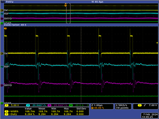
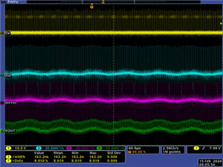
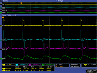
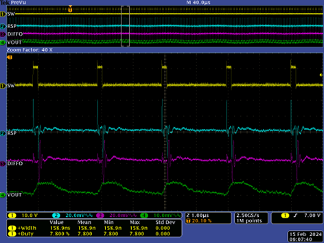
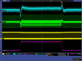
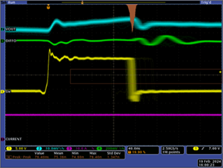
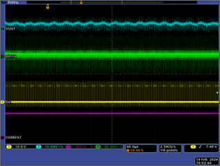
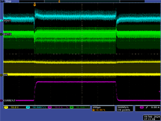
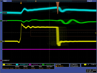
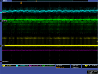
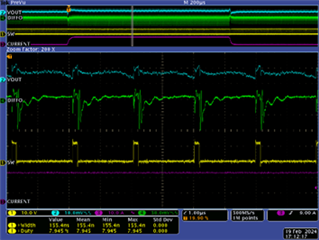
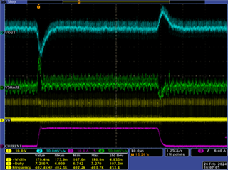
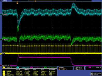
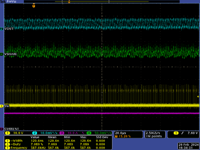
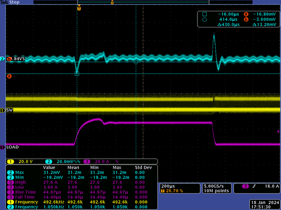
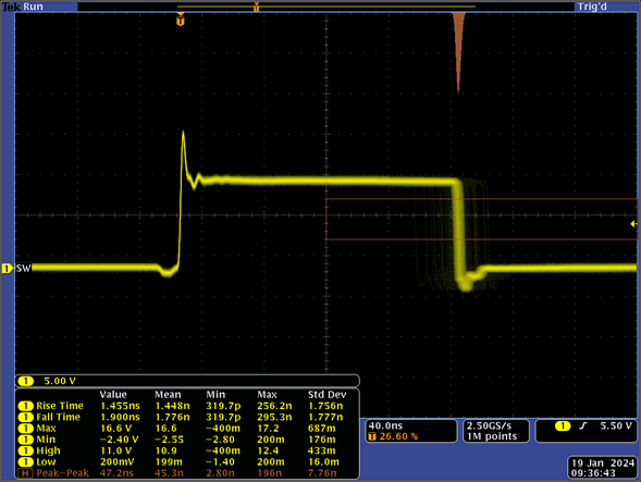
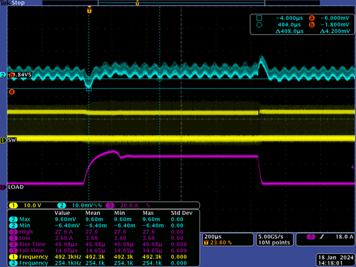
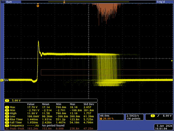
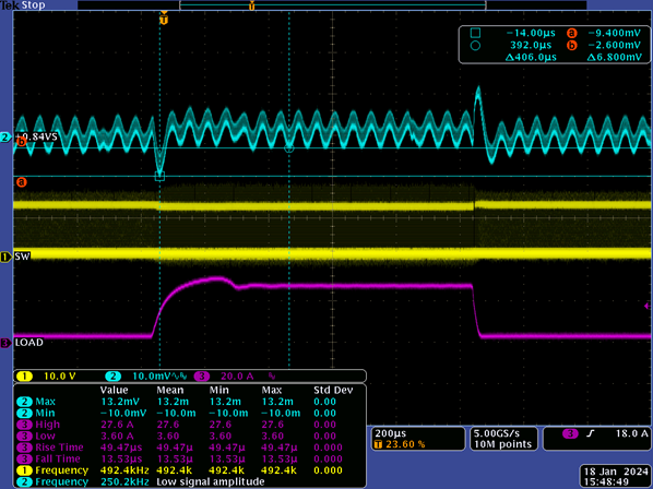
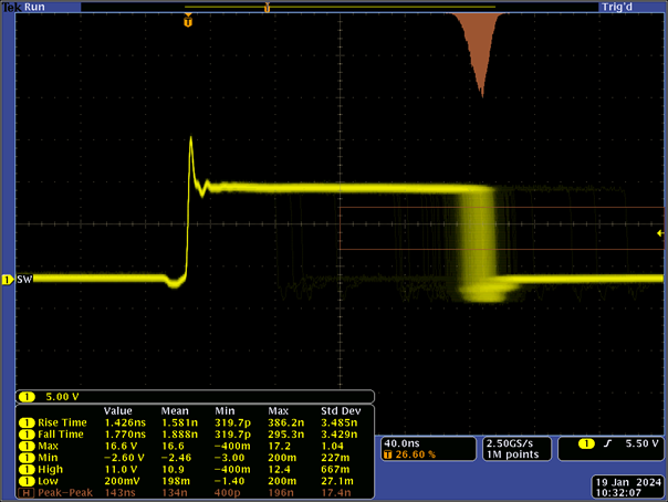
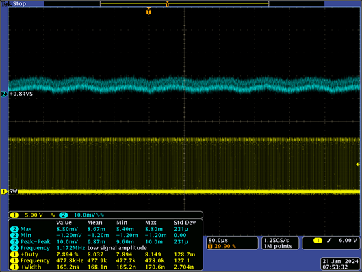
Issue 2: On top of the switch node synchronized output voltage ripple, there is a low-frequency wave, this indicates the control loop is oscillating although with small amplitude. Where does this oscillation comes from, even when the power supply loop gain is designed and tested to be stable with sufficient phase and gain margins? 

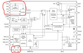
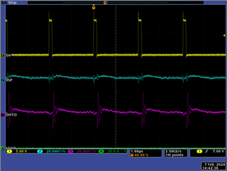
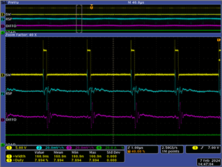
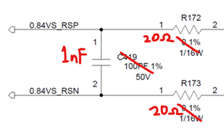
50Ω is placed series on RSN and RSP lines, with 100pF between them as a remote sense filter. The circuit has been tested with different set of instruments i.e. power supply, electronic load, oscilloscope, probes, and still exhibits the same oscillating behaviour, thereby eliminating the factor of instruments loading or back-driving the control loop. An attempt to bypass the remote-sense amplifier is done, but the low-frequency oscillation is still present (see Case 4 below).

By adjusting the compensation network, below are design and measured data for three cases of loop gain bandwidth on the same power supply.

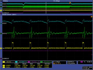
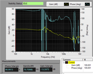
Case 1: Low Bandwidth, Low Jitter, With Low-frequency Oscillation

Attached <SLURB05 — TPS546C20A and TPS546C23 Excel Calculator and Layout Checklist>

TPS546C20A_TPS546C23_Calculator_Checklist.xlsx

R1

3.74kΩ

C1

1.8nF

R2

619Ω

C2

3.9nF

R3

10kΩ

C3

100pF

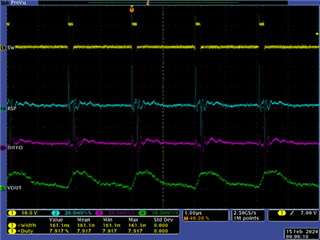
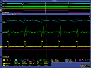
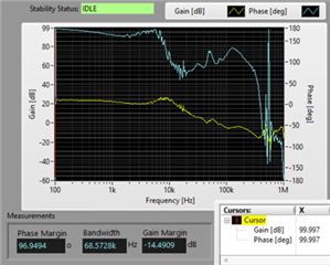
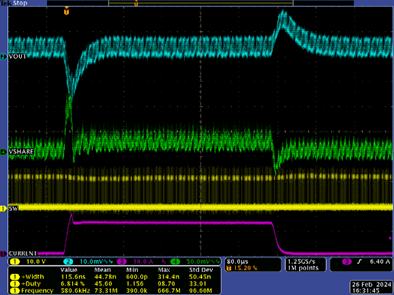
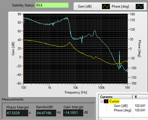
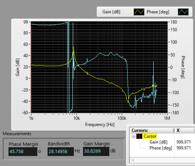
Case 2: High Bandwidth, High Jitter, Also With Low-frequency Oscillation

R1

3.74kΩ

C1

10nF

R2

10Ω

C2

3.9nF

R3

10kΩ

C3

100pF

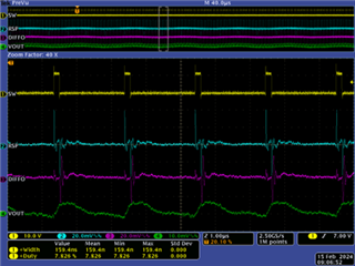
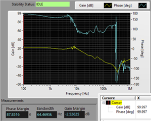
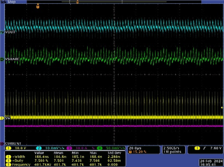
Case 3: Medium Bandwidth, Medium Jitter, Also With Low-frequency Oscillation

R1

3.74kΩ

C1

3.9nF

R2

10Ω

C2

3.9nF

R3

10kΩ

C3

100pF

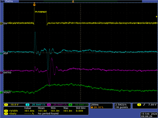
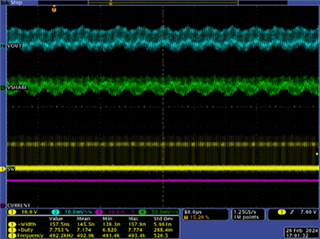
Case 4: Bypass Remote Sense Amplifier (disconnecting DIFFO, RSN, RSP pins and shorting output directly to compensation network)

Still With Low-frequency Oscillation

Compensation network follows Case 1

R1

3.74kΩ

C1

1.8nF

R2

619Ω

C2

3.9nF

R3

10kΩ

C3

100pF

  • Hey Kai,

    It looks like the device's feedback network is being coupled on to some low frequency noise that is then amplified by the control signal based on the component selection. Is it possible that your layout has some high noise line traveling near the IC?

    Thanks,
    Caleb

  • Hi Caleb, 

    Thank you for responding. The layout is also one of my suspicions and my team and I are actively reviewing it. Nonetheless, I have three entirely different PCBs laid out with the same schematic design, and this oscillation is consistent across two newer PCBs, but not on the older one. During the test, all other circuits around the converter are offline, so the most likely source of noise is the inductor. Following general best practices, the remote sense lines are buried into the internal layers and runs far away from the inductor.

    PMBus is not implemented and is left floating during this test.

    Please suggest if you think of any other factors that may be the cause. Is there possibility on something affecting the internal linear regulator or oscillator?

  • Hey Kai,

    Another thing I can think of is your placement/capacitance value of filtering caps on BP6, BP3, AVIN, PVIN. Can you verify that you have the correct capacitance outlined in the datasheet and that the filtering caps are placed on the same layer as the IC and are as close as possible to the device?

    Thanks,
    Caleb

  • BP6: datasheet recommends 2.2µF and additional 100nF to PGND, applied 4.7µF and 0.1µF to PGND

    BP3: datasheet recommends 2.2µF to AGND, applied 4.7µF to AGND

    AVIN: datasheet recommends 1µF to PGND, applied 1µF and 0.1µF to PGND

    PVIN: applied 8x10µF, 1µF and 0.1µF to PGND

    The layout was designed to be as close to the evaluation board as possible.


    My next things to try are:

    • rewire direct to local sense, bypassing the long remote sense traces completely
    • complete ground-up revamp of the compensation network using different combinations of R and C to achieve the same loop gain
    • build my schematic design onto the eval board TPS546C20AEVM1-746 to test

  • Hey Kai,

    I think those are all valid ways forward. I'll consult with my fellow engineers for more ideas on Monday. One question, what is the frequency of the noise? and does the noise frequency change or is it constant?

    Thank you,
    Caleb

  • The oscillation seems to be approximately 10kHz to 12kHz, consistent across all compensation network set

  • Hello Hoo, 

    good that you have a board that does not have this issue. do you know the Delta between them. 

    things to look for are: 

    1. Keep signal components local to the device, and place them as close as possible to the pins to which they are connected. 
    2. Feedback network should be noise free 
    3. AGND is very important to be noise free as well
    4. COMP, if there is any signal affecting, it will destabilize it 
    5. minimize the SW Nnodre POUR, it is larger then it needs to be. Minimize the loop area formed
    6. the same as above for the BOOT
    7. reduce the SW node Spikes by the input bypass capacitors of the power-stage. The bypass should be placed as close as physically possible to the PVIN and PGND pins.
    8. Additionally, a high-frequency bypass capacitor in smaller package (a 0402 package as in the Datasheet recommendations)  on the PVIN pins can help reduce switching spikes. This capacitor which can be placed on the other side of the PCB directly underneath the device to keep a minimum loop.
    9. Place the BP6 high frequency bypass capacitors as close as possible to the device pins, with a minimum return loop back to ground. The BP6 bypass capacitor carries a large switching current for the gate driver. Bypassing the BP6 pin to PGND with a low-impedance path is very critical to the stable operation of the devices.
    10. AVIN should be noise free. The AVIN and BP3 pins should have good local bypassing. That can be achieved by Place bypass capacitors as close as possible to the device pins, with a minimum return loop back to ground.
    11. as you mentioned above, the sensing components need to be clean and isolated  

    Thanks 

    Tahar

  • Hi Hoo, 

    More comments about the plots you provided besides layout, the jitter typically is a results of oscillation on the VOUT and the feedback network. The jitter may be side effect of stability due to that noise. 

    Many be further tuning is required, the device uses voltage mode control with input feedforward

    Looking at the bode plot, the systems is stable with good Phase and Gain Margin. I do not know what is going on at 10KHz, i see lots noise measurement. 

    Is is possible to compare the Bode with the old desing that does not have the issue, if that 10KHZ noise gone, then that may lead the issue. 

    Thanks! 

    Tahar

  • Hi Tahar, thank you for the advice. Here is the plot from the old board side by side with the oscillating new one. The schematic and BoM components are exactly the same as case 1, with the exception that the old board has another TPS546C20A stacked for 2-phase operation.

    Old Case 1

  • Hello Hoo, 

    The load step on the case 1 is very different from the old board, what is causing the load step to curve during a step up ( rise) vs a clear clean rise with clean edge on the old board? 

    The device look stable except the oscillations on VOUT on the new board

    On the bode, yes I can see a difference, at 10KHz the old board does not has as much noise. 

    We need trace where this 10KHz Noise is coming from, ,do you have anything in the board that is switching at 10Khz or has harmonics at that frequency? 

    Thanks! 

    Tahar

  • HI Tahar,

    The old board was tested with a different electronic load to generate the load step. Doing the same with the new board results in such:

    The oscillation is still there, unrelated to how clean the load step is. 

    During the tests, all other circuits around the converter are offline. The power converter is completely isolated from other circuits. 

    • input: disconnected from main 12V bus and wired out to external power source 
    • output: load BGA device is completely removed from the board, leaving only bypass capacitors on the back side 

    The circuit has been tested on different lab benches, different instruments, at different locations but exhibit the same oscillation, making the oscillation unlikely to be coming from an external source. The only likely source of noise is the inductor of the converter itself, but remote sense traces are buried into the internal layers and runs far away from the inductor.

  • An update: I overhauled the entire compensation network design with new R and C. The 10kHz-15kHz oscillation is still present.

    Case 5: Medium Bandwidth, Low Jitter, Also With Low-frequency Oscillation

    R1

    3.74kΩ

    C1

    10nF

    R2

    100Ω

    C2

    10nF

    R3

    3.74kΩ

    C3

    270pF

  • Hello HOO, 

    Thank you for taking the plots, the systems looks stable to me if you ignore the 10KHz oscitations. The device recover very well to the load step. The oscitation looks to me  ore of noise coupling into it.  

    1. Investigate SW noise: Can you please capture something similar to this around 1us to 10us time scale ? this picture here is taken on an 2PH EVM. I want to see how this is related to SW node, How out of sync this is. I do not know if this is just voltage ripple and expected due to Switching of the device, or it is out of sync with the SW.     

    2, Investigate Noise coupled into SNSE pins: Now if this noise and not related to SW it is not in sync with it, can you see if you can measure on RSP and RSN near to the IC and compare it with measurement at the location of the sensing with respect to AGND ( to see how effective the clean the Kevin of the remote sense. The reason for this measurement is to look for noise on the sensing pin and that may affect ramp as below. The jitter you send me in your last post does not look that bad. but it can be noise into this remote sense trace. Typically to solve of recue  this you can add coupling cap about (1nF capacitor)  between the RSP and RSN pins to improve noise immunity. You can try that and see make a difference. 

    3. check AGND vs PGND, they may be bouncing at 10kHz frequency. AGND need to be clean and noise free and the layout connection as below. 

    Thanks 

    Tahar

  • Hi Tahar,

    I took some scope captures from the design of Case 5 shown above. The oscillations appear smaller here because of the 20mV/div scale compared to 10mV/div above. Will continue to review the layout in addition to your earlier points. 

    No Load 18A load

    Duty cycle variation

    Lowest Duty Highest Duty
  • Hello Hoo, 

    Thanks for the plots, that helps, It looks like the oscitations are out of sync with SW node. and the voltage ripple is within our expectations. for this side we are good. 

    Now on the RSP plots, are you measuring neat to the IC or at the remote sense location? It will be good to look at both to see if there is any delay. 

    How about the experience of adding ~1nF cap between the RSP and RSN pins? if possible to do, it will be good to investigate. 

    Thanks! 

    Tahar

  • Hi Tahar,

    Apologies for the slower response, due to spring festival in the Asian region.

    For RSP and DIFFO, the probe is nearest to the IC immediately on an exposed component pad or test point as shown in the photograph.

    I have replaced the remote sense network to 20Ω and 1nF as such:

    Here are the scope captures, unfortunately the oscillation is still observed:

    SW, RSP, DIFFO: nearest to IC

    VOUT: remote sense location, probed on top of decoupling MLCC

    The ringing on RSP and DIFFO is quite large, is this a normal observation? Should it be expected it to be similar to VOUT on the remote sense location?

  • Hello Hoo, 

    The fact the SNS pin is seeing the oscitation and it is well in phase with the VOUT. Yhis tells me that this is noise coupling.  

    in addition to the layout tips i provided in my previous posts, consider looking at the power return loop on your layout, may reducing that loop will help on reducing this coupling. 

    Thanks !

    Tahar

  • Hi Tahar, 

    Well noted on the layout advices, will thoroughly review it but we can only see the new result on the next PCB revision.

    I built my designs onto TPS546C20AEVM1-746 Two, Separated Single-Phase Evaluation Module and made some measurements.

    [Resolved] Issue 1: The flat loop gain in the low-frequency region has become a -20dB/decade slope, correct as expected. Using the test points on the evaluation board revealed that signal injection wires may introduce impedance that distorts the loop gain plot. This issue is fixed in my prototype PCB when the probe and signal injection wires are shortened significantly. Correct loop gain measurements can now be acquired.

    Issue 2: The small oscillation is also present in the evaluation board. Similar ringing is also observed on DIFFO pin. This points to PCB layout being an influencing factor, instead of compensation design. Nonetheless, this may also entirely be a non-issue as the capability of the power supply to regulate is not impaired. The only downside is that additional tolerance needs to be allocated to account for the low-frequency ripple. 

    -

    Compare with Case 3 above

    R1

    3.74kΩ

    C1

    3.9nF

    R2

    100Ω

    C2

    3.9nF

    R3

    10kΩ

    C3

    100pF

    -

    Compare with Case 5 above

    R1

    3.74kΩ

    C1

    10nF

    R2

    100Ω

    C2

    10nF

    R3

    3.74kΩ

    C3

    270pF

  • Hello Hoo,

    Good to see issue 1 is resolved. 

    For the issue 2, do you see the same thing on TI EVM as you board ? because this may roll out the Layout to be the issue. 

    Here is what the default EVM measures? with  0.9-V Output at 12 VIN. Are you see the same thing? the reason i asked, may be we need to make some changes on the LC to find a sweet spot. I agree with you, this looks low frequency that is not related to Stability based on Bode and transient, but it affect the accuracy. 

    Thanks 

    Tahar

  • Hello Tahar,

    Issue #2 persist on the evaluation board when built with my design. I did not manage to measure the default setting of the eval board as it was used for another design before I made changes.

    I have new observations after further debugging in search for the root cause. When the switching frequency is adjusted, the oscillation goes away. 

    f_sw = 403kHz (RT=49.9kΩ) f_sw = 500kHz (RT=40.2kΩ) f_sw = 605kHz (RT=33.2kΩ)

  • Hi Hoo, 

    It looks like there is resonant point.  Changing the frequency away from that resonant point, the loop and the device is able to operate just fine and correct for it. That is a very good observation. The 10K oscillations is very well noticeable at the noise frequency.  It is affect the loop and the device is not able to coop with it well and correct for it. At that frequency, the device does not look unstable at all. But if you want to have better regulation as you mentioned before , you can shift the frequency as you already proved.

    Thanks! 

    Tahar

  • Hi Tahar,

    Thank you for the continued support. We are moving forward by designing at higher switching frequency of 600kHz. Nonetheless, it would be great if TI could provide additional insights to the root cause of this oscillation, so that in the future, we may make an informed decision of avoiding 500kHz when using TPS546C20A. 

  • Hello Hoo, 

    Since this shows on the EVM that that not much related to the layout. 

    The other observation I have on the bode plot taken, the gain is at ~20dB at lower frequencies where as typically that can be a little higher to around 40 to 60dB at freq<2KHz. see blow how typically shpuld look like below. 

    Thanks 

    Tahar

  • Hi Tahar, 

    The bode plot you mentioned about is issue #1 which is related measurement setup, particularly the length of probes and wires for the injection and scope.

    Evaluation Board TPS546C20AEVM1-746

    (no wire, direct probe)

    Prototype 

    (short individual signal wires)

    Prototype
    (long twisted signal wires!)

    Thanks!

  • Hello Hoo,

    That make sense, with longer wires the signal injected attenuated.  

    Thanks!

    Tahar