A related question is a question created from another question. When the related question is created, it will be automatically linked to the original question.
If you have a related question, please click the "Ask a related question" button in the top right corner. The newly created question will be automatically linked to this question.
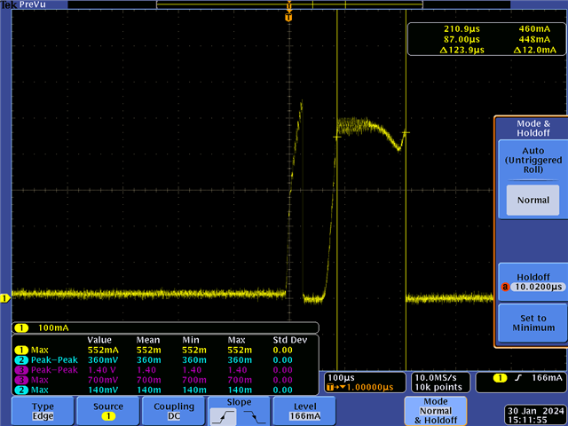
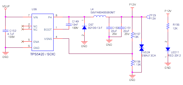
Do you have the schematic for us to check? What is the load condition for the waveform you captured? Also is 34V the maximum input voltage? As TPS5420 is a 36V device with 40V absmax, please make sure the voltage you applied on the Vin pin of the IC is within its limit.
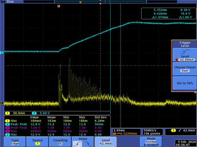
The current seems to be less than the image you shared earlier. The inductor current is necessary to build up the voltage on the output capacitor. And during the startup, it looks like the SS ramps a little quick initially and large duty cycle is created to let the inductor go high. Will this phenomenon affect your system design? Or you just want to understand what's going on?
I think you need to take a look at TPS2375 as well. From the startup waveform of TPS5420, the behavior looks good to me. Suggest you can create another post titling TPS2375 and the experts from their team will help you.