This thread has been locked.

If you have a related question, please click the "Ask a related question" button in the top right corner. The newly created question will be automatically linked to this question.

TPS23758: Trying to change the TPS23758 Output to 24V shows unexpected behaviour

Part Number: TPS23758

Hello,

I wondered, if it is generally possible to get a 24V output version of the TPS23758 circuit.

Therefore the transformer (Wuerth 750318525) would have to be changed to Wuerth 750319214 (Same footprint, same topology, different transformer windings ratios).

We ordered the "TPS23758EVM-080" and the 750319214  transformer and made the transformers interchangeable. The components on the output side were exchanged for higher-voltage rated ones. According to the datasheet of the TPS23758 the feedback voltage divider can be left as it is because

original: V_out = (R19 + R24) / R24 * V_REFC * N_(SEC->AUX) = 236.5/36.5 * 1.75 * 0.445 = 5.03V

adaption: V_out = (R19 + R24) / R24 * V_REFC * N_(SEC->AUX) = 236.5/36.5 * 1.75 * 2.14 = 24.48V

Transformer comparison:

Original Transformer: https://www.we-online.com/components/products/datasheet/750318525.pdf

Replacement Transformer: https://www.we-online.com/components/products/datasheet/750319214.pdf


Testing is done via the external adapter and VIN = 18V. However, the TPS23758 seems to have a problem with the reduced primary inductance (changed vom 150µH original to 65µH in the adaption). The output regulates to about 10.5V, the voltage on the FB-Pin is 0.75V instead of 1.75V. Increasing the switching frequency up to 680kHz did not change the behaviour of the circuit. The converter goes in a kind of makro on/off state which depends on the startup timing (CSS capacitor).

Please note the attached image:

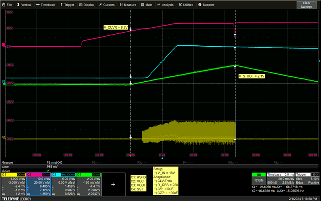
Converter starts switching, and the output rises. The voltage on the FB pin is around 0.75V (not shown) and stays there during the switching period (C1 on). This continues until SST reaches its termination value of 2.1V which forces the bootstrap startup current source to stop and therefore the output voltage to begin to reduce.

Changing the input voltage away from 18V towards higher voltages reduces the output voltage. 

Also note the detailed waveforms in the following image (changed rise time of FET via SRR resistor).


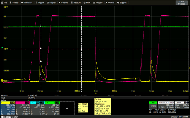
The converter shows some starnge behaviour every second cycle, which is always shorter (maybe overcurrent error?)

Any help regarding the above issue would be very much aprreciated.

  • Hi Maximilian,

    Thanks for reaching out.

    I am wondering if you also changed the APD's voltage divider resistance. You may need APD = H to enable the dc/dc converter operating at a lower input voltage. 

    When using a 18-V adapter, APD is 18V/(200k+9.09k) = 0.78V. You may need to change the R25 to 20k to make sure APD is higher than 1.58V. 


    Besides, did you try a PSE as input or a higher AUX input voltage like 48V?

    Best regards,

    Diang

  • Hi Diang,

    thank you for your quick answer and your tips.

    The evalboard also works in original mode (5V out) with 18V adapter voltage, so this is not the problem.

    I just tested the adapted board (24V transformer) with 48V adapter input and the results is as follows:

    The TPS23758 now gets hot during operation with higher input voltage.

    The output settles at 3.5V. The drain of the internal FET does not switch on fully. My guess is that is because of current limiting: V(R_SNS) > 0.55V = V_CSMAX (datasheet). As the inductance L reduced during transformer change, the current can rise faster as u = L * di/dt and therefore triggers the current limiting.

    Rising the current liimit by reducing the shunts (R13/R14) would be an option but stress the IC even more.

    Can we somehow adapt the circuit to allow the 24V transformer to work with the TPS23758?

  • Hi Maximilian,

    Thanks for your updates on the 48-V input test.

    I was also considering the flyback transformer may get flux density saturated if working at a low adapter voltage at 18-V. But looks like at 48-V there still have some issues.

    I agree with your concern about the CS voltage reaching to the 0 duty cycle with a 65-uH inductance in the peak current mode control, but I do not think it will cause the converter could not work at all.

    Sorry that I just saw your parameter adjustments.

    D8 & Q1 and snubber: I think 26-V rated D8 is not enough. The secondary FET drain-source voltage will be Vout + Vpri/N_p*N_s + overshoot = 24-V + 57V/1.2*1 + overshoot. Which will be much higher than the 5-V case. If the voltage rating is too low, it may cause the over current issue like the large CS voltage.

    R_SRR 10->120 Ohm: it may be a risk. Considering you have FET on the secondary side and a high turn-off resistance may cause longer shoot-though time which may trigger an overcurrent event.

    R_FRS 60.4->22k Ohm: increasing the switching frequency will cause increased switching loss and temperature rise on the chip. 

    Best regards,

    Diang