This thread has been locked.

If you have a related question, please click the "Ask a related question" button in the top right corner. The newly created question will be automatically linked to this question.

TPS546C23: Multiple PMBUs Communication

Part Number: TPS546C23
Other Parts Discussed in Thread: TPS546A24A

Hi Team,

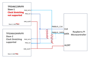
I have  done a design using TPS546C23RVFR and TPS546A24ARVFR.Both device PMBus lanes are connected to a single mater via common PMbus.Looks TPS546A24ARVFR device supports PMBUs clock stretching feature ,but TPS546C23RVFR  device doesn't support clock stretching feature.Will this PMBus communcation work with 2 slaves and master?.i have attached below mater slave connection.
Please check and let me know what can be 

/cfs-file/__key/communityserver-discussions-components-files/196/pastedimage1708452075243v2.png

Datasheet  TPS546C23RVFR  : /cfs-file/__key/communityserver-discussions-components-files/196/pastedimage1708452165879v3.png

Does this both device support clock stretching TPS546C23RVFR and TPS546A24ARVFR ?

Regards,
Sujith M

  •  

    Will this PMBus communcation work with 2 slaves and master?

    Yes.  PMBus was designed as a multi-controller (Master) multi-target (slave) protocol.  While there is some added complexity coordinating between controllers on the same bus, as long as targets have unique addresses, there is no added complexity having multiple targets sharing the same bus.

    Does this both device support clock stretching TPS546C23RVFR and TPS546A24ARVFR ?

    The TPS546C23 does not clock-stretch.  That is, the target does not extend the CLK low period of any in-coming transactions.  It is tolerant of clock stretching by another device on the bus.

    The TPS546A24A does clock-stretch, but only during transactions that have addressed its target address and never during the address portion of the transaction.  For more details about the exact bits within a transaction that the TPS546A24A may clock-stretch, see the TPS546A24A datasheet.

  • Hi Peter,

    Yes.  PMBus was designed as a multi-controller (Master) multi-target (slave) protocol.  While there is some added complexity coordinating between controllers on the same bus, as long as targets have unique addresses, there is no added complexity having multiple targets sharing the same bus.

    Ok.

      It is tolerant of clock stretching by another device on the bus

     1)Could you please explain to me how this device TPS546C23 is tolerant of clock stretching by another device on the same bus?

    2)) Does clock stretching supported device TPS546A24A  will interrupt the functionality of TPS546C23 ?

    3)Is there any issue if we tie all PMIC ALERT pin ?

    I want to make sure that my PMBus architecture is proper ? Please see below image

    /cfs-file/__key/communityserver-discussions-components-files/196/pastedimage1708532383015v1.png

    Regards,
    Sujith M

  • Hi Sujith,

    Peter will reply you later.

  •  1)Could you please explain to me how this device TPS546C23 is tolerant of clock stretching by another device on the same bus?

    Several things allow the TPS546C23 to be tolerant of clock stretching by another device.

    1) Clock stretching extends the CLK low period, delaying the rising edge of CLK.  It does not add additional edges to CLK.

    2) The TPS546C23 does not have an internal clock synchronized to the incoming CLK, it responds only to the falling and rising edges of the incoming CLK.  As long as the CLK low period is greater than 300ns and no more than 25ms and the clock high period is at least 300ns, the CLK need not be constant.

    3) When a PMBus transaction targets a different address than the one used by the TPS546C23, it ignores all data on the bus until the next START event (falling DAT while CLK is high).

    4) The TPS546x24y family of devices only clock stretches during specific bits within data bytes when transactions are addressed to its device address.

    2)) Does clock stretching supported device TPS546A24A  will interrupt the functionality of TPS546C23 ?

    No.  The TPS546x24y family of devices will not interfere with the operation of the TPS546C23 device on a shared PMBus physical layer.  This has been done many many times with other customers.

    3)Is there any issue if we tie all PMIC ALERT pin ?

    It is common that all ALERT pins are connected together and the ALERT is pulled low when any device wants to issue an ALERT.  SMBus uses the Alert Response Address (ARA) to allow the system to identify which device is asserting ALERT.  A device which supports ARA, including both the TPS546C23 and TPS546A24A, asserting ALERT will respond to a transaction starting with the Alert Response Address + Read Bit with it's device address, and will then release the ALERT.  This allows the system identify the device generating the ALERT to follow up by reading STATUS_BYTE or STATUS_WORD.

    Standard bit arbitration will cause the device with the lowest Target Address to win a contested bus if multiple devices are asserting alert.  After successfully responding with it's address, a device should released it's ALERT so the system can know if it needs to poll ARA again for more alerting device addresses, or begin reading STATUS information.

    I want to make sure that my PMBus architecture is proper ? Please see below image

    Your graphic has CLK and DAT of Device 2 - TPS546A24A swapped.

    All three devices should have their DAT pins connected to the same net

    All three devices should have their CLK pins connected to the same net

    Both devices should have their ALERT pins connected to an interrupt digital input of the Raspberry Pi Microcontroller.

    Also, I would not recommend using address 0x02 for the TPS546C23, this is a reserved address for CBUS per the I2C specification, and the TPS546A24A can not be pin programmed to address 0x03.  In order to avoid reserved addresses, and select an address which can be programmed by both devices, I would recommend using addresses 0x12 for the TPS546C23 and 0x13 for the TPS546A24A.

  • Hi Pitter,

    Thanks for your detailed information.

    Your graphic has CLK and DAT of Device 2 - TPS546A24A swapped.

    All three devices should have their DAT pins connected to the same net

    All three devices should have their CLK pins connected to the same net

    Both devices should have their ALERT pins connected to an interrupt digital input of the Raspberry Pi Microcontroller.

    /cfs-file/__key/communityserver-discussions-components-files/196/pastedimage1708615558778v1.png

    Attached architecture is for pictorial representation only. In the actual design we followed salves addressing as per device datasheet address chart.

    Regards,
    Sujith M

  • Hi Sujith,

    Peter will respond to this by tomorrow.

    Thank you,

    Calan

  • Sujith,

    Yes, that updated graphic looks correct.

    If this as resolved your issue, please click on the "This has resolved my issue" button and we will close out this thread.

    If you have another issue or question, please "Ask a new question" with a new thread.

    I will be out of the office for the next week, so another applications engineer may assist you while I am out.