This thread has been locked.

If you have a related question, please click the "Ask a related question" button in the top right corner. The newly created question will be automatically linked to this question.

TPS389006-Q1: TPS389006004-Q1 ACT wave fails to be high

Part Number: TPS389006-Q1

Hello expert,

Are there some possibility to cause ACT wave from 1 to 0? 
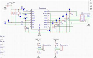
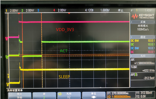
Situation 1: ACT is pull up to VVDD_3V3 through R8, As shown in the following picture, ACT is driven to 0 about 1.5ms and than turn back to 1. 
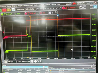
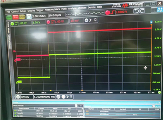
Situation 2: ACT is pull up to VDD_3V3 directly. The ACT will not be drive to low but there is a high noise spike.
Best regards,

wenting 

  • Hello Wenting,

    What is the state of the sleep pin? Act being pulled low and the noise might be caused by the BIST test on power up. Act should be directly connected.

    Best,

    Walter

  • Hello Walter,

    the Sleep in is high. and if the ACT is connected to VCC through a pull-up resistor, will there be some issues?

    Best regards,

    Wenting

  • Hello Wenting,

    There should not be an issue with the schematic and pullup resistor.

    Please see this post for more information.

    https://e2e.ti.com/support/power-management-group/power-management/f/power-management-forum/1190965/tps389006-q1-act-is-pulled-down-by-tps389006-q1

    Best,

    Walter

  • Hello Walter,

    The customer follows TDA4 PDN-3M design.  ACT comes from a wake-up signal (like KL15), which is not easy to control to follow VDD timing, If the customer short ACT to VDD. Is there a timing issue? 

    Best regards,

    wenting 

  • Hello Wenting,

    There should not be a timing issue if ACT is connected to VDD

    Best,

    Walter

  • Please be advised that TDA4x PDN-3x v0.23 (or higher) bock diagram has changed the ACT & VDD connections on TPS389006004-Q1 (Safety Voltage Supervisor aka SVS) as follows:

    The SVS VDD supply connections need to be changed from “Always ON” VCCA_3V3 (=VSYS_3V3) to a “PMIC controlled” power rail to enable resetting of an asserted IRQn signal by power cycling SVS devices. During functional testing, it was discovered that an SVS’s asserted IRQn could not be reset if MCU processor I2C comm with SVS devices is lost. This will happen if a MCU Power Error occurs (i.e. fault on a MCU supply) since this will cause the PMIC PFSM to transition the system to the desired Safe Recovery state (powers down all SoC supplies). However, if the SoC PDN’s input voltage (VSYS_3V3) remains energized, then the energized SVS devices will maintain an asserted IRQn and the system will not be able to execute a SoC cold boot attempt due a previously asserted IRQn will cause the PMIC to abort an SoC power up sequence attempt. A SVS device power cycle will reset an asserted IRQn signal, enabling the desired SoC cold boot attempt. By replacing “Always ON” VCCA_3V3 supply connections with a PMIC controlled power rail (VDD_MCUIO_3V3 sourced from PMIC's LDO2 Vout), the SVS devices will have a power cycle event upon entering the Safe Recovery state (per table below). If a fault occurs on a Main domain supply, the PMIC will transition the system to MCU Only state which allows MCU I2C comm to evaluate & potentially log the fault source. The MCU can use I2C comm to clear an asserted IRQn if a system cold boot attempt is desired to try restarting into the Full Active state since a fault might clear if it’s due to a random noise event or temperature dependent.

    The SVS “ACTive” input connection will need to be changed from "SOC_PWR_EN" connected to the PMIC Enable input to the SVS's VDD supply.  The new VDD_MCUIO_3V3 supply connection is enabled after VSYS_3V3 as part of the SoC power up seq. This change will avoid driving a high logic signal on ACT input while the device is not powered up.

    PDN State: Active                           MCU Only                      Safe Recovery 

                       Main supplies = ON     Main supplies = OFF     Main supplies = OFF 

                       MCU supplies = ON     MCU supplies = ON      MCU supplies = OFF
                       SVS-A = ON                 SVS-A = ON                  SVS-A = OFF
                       SVS-B = ON                 SVS-B = ON                  SVS-B = OFF