This thread has been locked.

If you have a related question, please click the "Ask a related question" button in the top right corner. The newly created question will be automatically linked to this question.

LP8863-Q1: Unable to drive over 40mA

Part Number: LP8863-Q1

Hello!

I am attempting to drive an LED string at near 900mA using the LP8863 in the following setup:

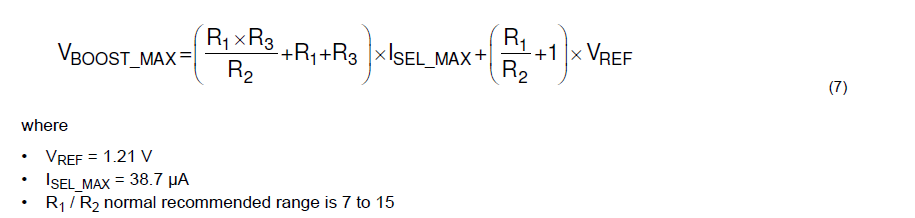
  • SEPIC mode with 24V input and 23.2V max output with RFB1=150k and RFB2=470k.
  • 400 kHz switching frequency
  • 33uH coupled inductor, 10uF coupling capacitor, 33uF polymer + 10uF ceramic capacitors on input and output.
  • 141mA current limit per channel (Riset = 22k)
  • All 6 channels are connected in parallel.
  • Control through I2C

Over I2C, the device is configured with:

  • PWM mode at full brightness (0xFFFF written to 0x28)
  • Initial current limit for each channel set at 0.72mA (LEDx_CURRENT = 0x0015)
  • Each LEDx_CURRENT register is incremented by 1 every 50ms and the value 0x0001 is written to BRT_DB_CONTROL to update

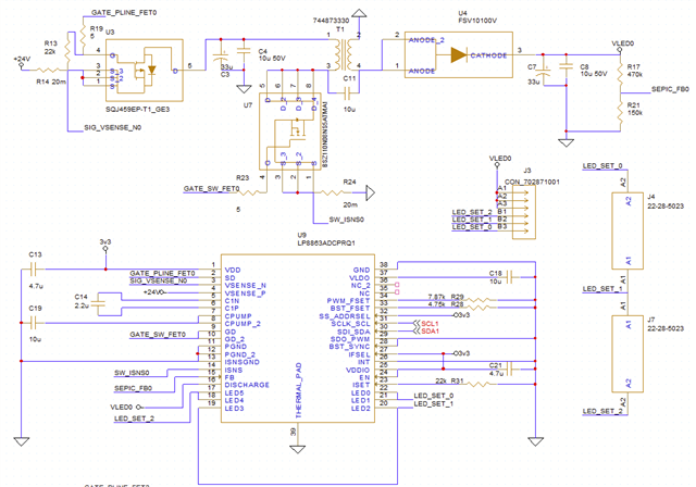
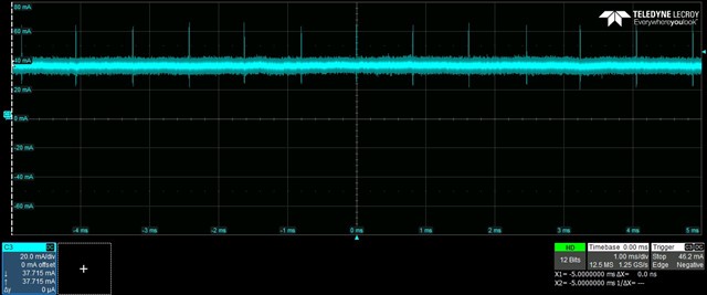
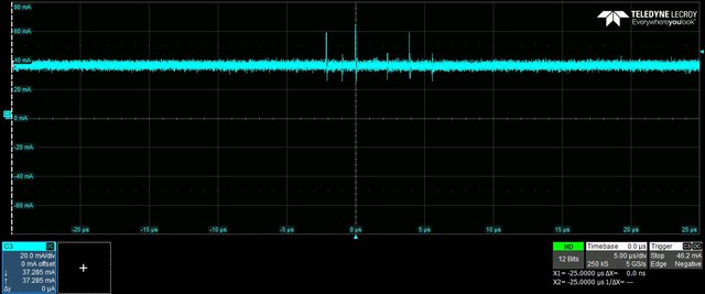
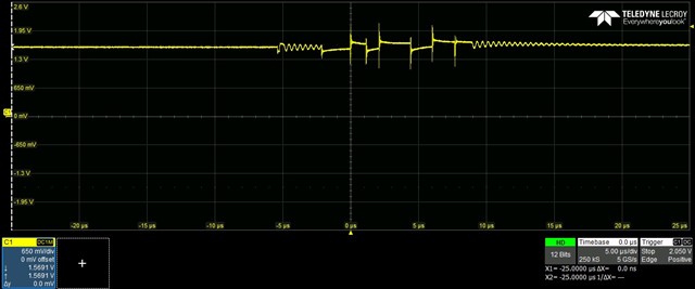
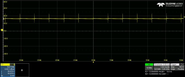
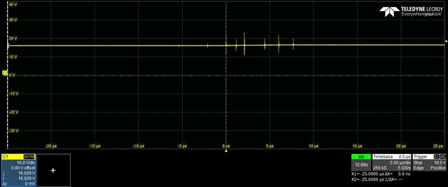
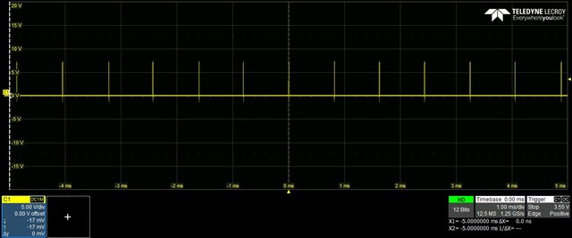
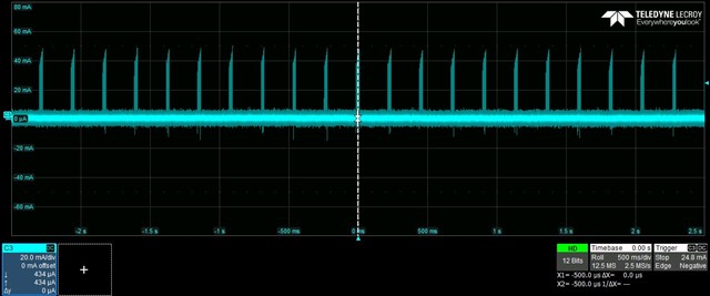
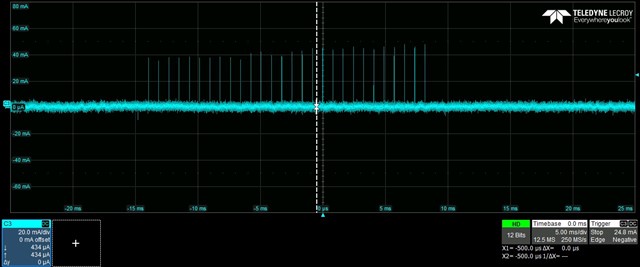
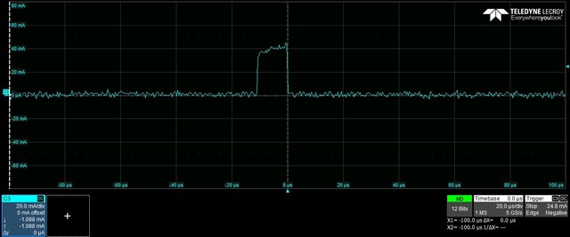
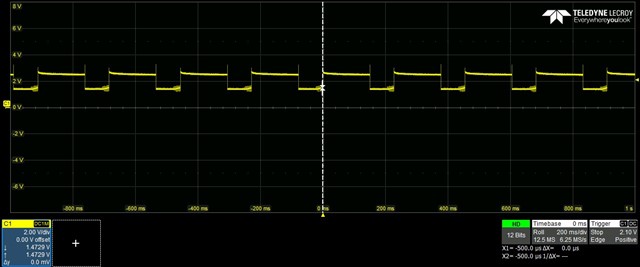
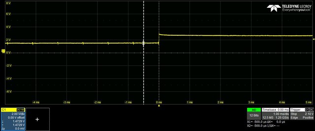
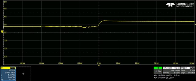
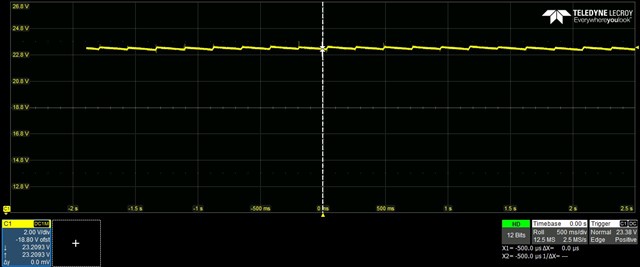
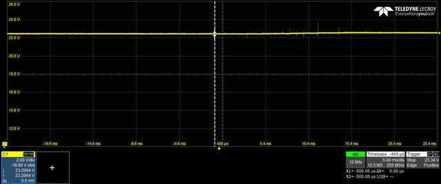
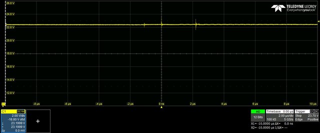
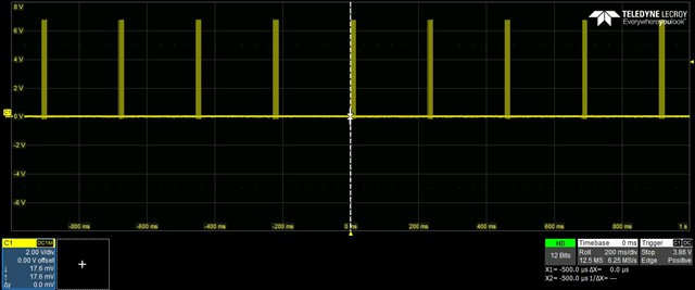
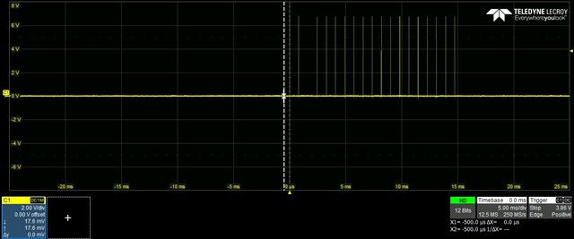
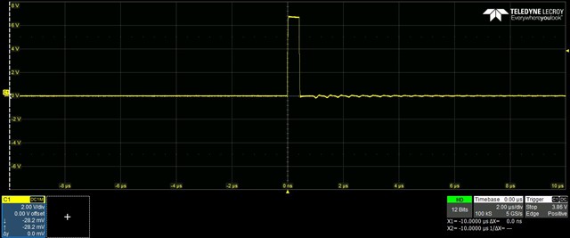
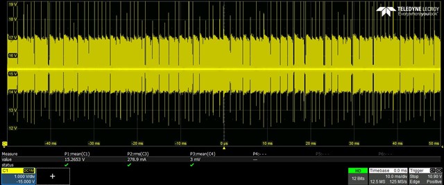
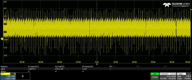
Initially, the LEDs show steady brightness. As current approaches 40mA the voltage ripple on the SEPIC output increases and has a frequency much lower than the switching frequency. At approximately 40mA the LEDs shut off and the voltage on the SEPIC output remains near the maximum voltage determined by RFB1 and RFB2. This occurs at the same LED current when driving with 1, 2, and 3 channels.

Continuously reading the status and diagnostic registers shows the device cycling through startup, and fault states repeatedly. This is accompanied by two interrupt status bits. First CP_STATUS and then BSTOVPL_STA
TUS. Loading the SEPIC output directly with a 180 ohm resistor produces stable voltage, and does not affect the LED current where these conditions occur, so it seems the SEPIC is capable of providing enough current.

Could anyone advise on where the problems may be?

  • Hi,

    could you pls share the schematic?

  • Hi Zhiqian,

    This is the schematic being used. Jumpers are place on J4 and J7.

    Thank you

  • Hi Vikesh,

    Zhiqian is currently out of office. He will reply to you by tomorrow. Thanks for your understanding.

    Best Regards,

    Steven

  • Hi, Vikesh

    depending on your description, CP_STATUS is reported, and it means that the there are some problem in charge pump.

    You can check with the output current/CP voltage in LED load and resistor load.

  • Hi Zhiqian,

    I have monitored the charge pump capacitor with a scope and confirmed it remains stable at 6.5V. Is there anything else that may cause this issue? I have also tried reconfiguring to a boost topology with no improvement.

  • Hi, Vikesh

    Pls help to catch the waveform in below signal for two load:

    Iout/FB/boost output/GD

  • Hi Zhiqian, here are waveforms at two different current settings. The first set is with 0x80 written to all LEDx_CURRENT registers. The second is with 0xA0 written. There are several timescales to show the behavior fully. All waveforms are with PWM set at 0xFFF (100% duty cycle). Thank you for your help.

    LED current waveforms at LEDx_CURRENT = 0x80:

    FB pin waveforms at LEDx_CURRENT = 0x80:

    VOUT waveforms at LEDx_CURRENT = 0x80:

    GD waveforms at LEDx_CURRENT = 0x80:

    LED current waveforms at LEDx_CURRENT = 0xA0:

    FB pin waveforms at LEDx_CURRENT = 0xA0:

    VOUT waveforms at LEDx_CURRENT = 0xA0:

    GD waveforms at LEDx_CURRENT = 0xA0:

  • Hi, 

    Depending on the waveform, the close loop is unstable, could you pls try to change the ratio of FB and add the output cap to have a try? 

  • Hi,

    Thank you for the suggestion! Do you suggest changing the FB resistors to higher or lower resistance? I also notice the FB pin is not regulating to 1.21V as the datasheet suggests it should. Will increasing the value of both FB resistors help this? I have tried adding additional capacitance (an additional 33uF polymer + 10uF ceramic) with the same issue.

  • Hi, 

    For our device, the ratio of FB pin is recommend in the datasheet, pls also calculate the boost output range if it can match the LED requirement.

  • Hi Zhiqian,

    I replaced Rfb2 with the recommended 170k and Rfb1 with 560k. Additionally, I modified the board to implement the SEPIC topology from the application note. I am still seeing the exact same issue. Is there anything else that may cause this? I can power the LEDs at full current if I connect directly to the output of the SEPIC, so the circuit is capable of regulating voltage and providing enough current. It is only when I attempt to control the LEDs with the LP8863 pins I run into this issue. Is there anything else that may cause this?

    Thank you,

    Vikesh

  • Hi, Vikesh.

    May you pls check with the output voltage of device during different current?

    And Let me explain my understanding, correct me if it is wrong.

    For your test, you can work for max current range, but when you transfer to low current, device is unstable?

  • Hi Zhiqian,

    I can provide a scope waveform of the output voltage later today. In my previous testing it was stable below the max threshold before 40 mA is reached. Apologies for being unclear - the problem is that I can only drive low current (below 40 mA) using the LP8863. Any current above 40 mA causes the issue. The full current test I referred to involved connecting my LED strip across the output voltage of the SEPIC (in the schematic between VLED0 and ground). This was to confirm the components in the SEPIC were capable of supplying the required current. When I connect the LED strip between VLED0 and the LEDx pins on the LP8863 I can still only drive up to 40 mA.

    Thank you,

    Vikesh

  • Hi Zhiqian, I have some more insight into the nature of the problem. In software I am gradually incrementing the current limit. I am monitoring the SEPIC output voltage, the headroom voltage, the FB pin voltage, and the ADAPT_BOOST_DIAGNOSTICS register.

    I notice the SEPIC output remains higher than the value in the ADAPT_BOOST_DIAGNOSTICS register. As current increases, the ADAPT_BOOST_DIAGNOSTICS register reduces in value while the output voltage, feedback pin voltage, and headroom voltage all increase.

    After the ADAPT_BOOST_DIAGNOSTICS register reaches 0, the feedback, headroom, and SEPIC output voltages all continue to increase. When current reaches near 40 mA headroom voltage is above 5.5V.

    It somehow seems like the SEPIC is stable, but not regulating to the right voltage. The voltage increases until another fault, like boost overvoltage is triggered.

  • Hi, Vikesh

    Thanks for your introduction.

    Could you pls kindly share the information about the min&max of LED forward voltage? Depending on your description, the device is failed to control the boost output.

    In another part, pls take the device off the PCB and soldering again to check if it is the assembling problem.

  • Hi Zhiqian,

    Here are waveforms of voltage across the LEDs and the headroom voltage. We are trying to drive the LEDs between a minimum of 13V and a maximum of 24V. I have tried replacing the part with a new IC but the issue persists. Do you have any thoughts based on these waveforms?

    LED Voltage:

    Headroom Voltage:

    Thank you,

    Vikesh

  • Hi, Vikesh

    As mentioned, could you pls changed the divide ratio of R1/R2 in the datasheet? increase the ratio to 7~15