This thread has been locked.

If you have a related question, please click the "Ask a related question" button in the top right corner. The newly created question will be automatically linked to this question.

LM5066I: No output when startup with load

Part Number: LM5066I

Hi TI,

I have a design with LM5066I to protect a power output to user. It is +48V at 16A max. I originally designed it to startup with no load, enable (EN) controlled by a digital signal (refer to LM5066I_original excel calculator) and it is working as expected. However, when I preloaded the user terminal with 16A before the eFuse is enabled, no +48V at the user terminal. I believed the MOSFET power is hitting the power limit threshold that I set to be 159W.

Using the excel calculator (refer to LM5066I_new excel calculator), I increase the power limit to 200W and startup load to 7A. I do not have much flexibility to change the MOSFET because I already have my board fabricated. With these conditions, the "recommended slew rate" field is "NA" but I can still set the dVdT rate on Vout to be 0.02V/ms to have a good SOA margin for the MOSFET. Is this something valid? The startup inrush current level is way below the load current and using SS mode seems useless. Switching to power limit mode is also not an option because of the MOSFET SOA. Is there anything else I can do to make the design work or changing MOSFET is my only option? Please advice.

I am also confused with the Start-up: FET Power graph in the calculator. If I startup with Vinmax=51.36V and Iload=7A, the max power is 359.52W but the graph shows 86W. Can you explain how it calculate the MOSFET power?

Thanks

LM5066i_original.xlsm

LM5066i_new.xlsm

  • Thanks for reaching out. We will get back to you by Thursday. 

  • Hi, can I get response on this question?

  • Sorry for the delay. 

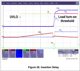
    As per the design calculator, load turn-on threshold is 39V.

    If this this data is correct, the design should power up with a 7A of constant current load at a load turn-on threshold of 39V. Please don't increase the power limit to 200W. Power limit should be kept at 159W as earlier. The MOSFET will not have adequate SOA margin during power up into short and short-circuit with 200W of power limit. If the start-up load id 7A with a load turn threshold of 0V, the design can't work. 

    VDS at the instant 7A of load applied = 51.36-39 = 12.36V

    Peak power loss = 12.36 * 7 = 86.52W. 

  • The turn-on threshold is the same as the UVLO that I set using the resistor divider. I assume the load is always connected at the user terminal and will be active immediately when the eFuse is turn on upon exceeding its UVLO threshold.

    With 159W power limit, I should limit the user load to be >159W upon startup, am I right? In other words, I cannot start up with 16A because with this the MOSFET power upon start up will be ~157W, very near to the power limit.

    What about the slew rate? Can I use 0.02V/ms slew rate since the recommended slew rate is "NA"

  • Please see the below image. UVLO threshold corresponds to VIN and load turn-on threshold corresponds to VOUT. Both are not same.

    Meaning of power limit is MOSFET VDS x IDS, not VIN x IIN.

    Please refer to the below app note, which explains the hot swap design procedure. 

    Robust Hot Swap Design (Rev. A) (ti.com)

    Reducing slew rate will not help here. If the recommended slew rate shows "NA", the selected MOSFET can't handle the power loss generated during start-up. This may lead to MOSFET damage. 

    Please use the PG signal to turn on the downstream loads. Otherwise, your MOSFETs can't support your requirements.