Hello,
Greetings!
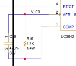
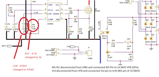
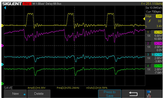
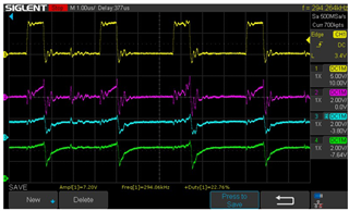
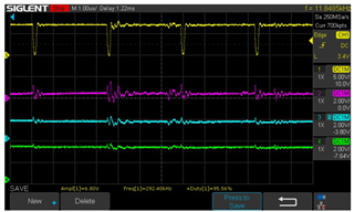
We are using UC3843 IC but facing some issue in PWM generating
PWM always having maximum duty cycle. So heavy current in the input side. How to reduce the duty cycle. Please advise

Thanks & Regards
Vijai
Hello,
Greetings!
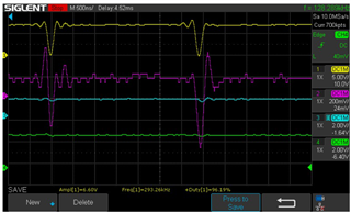
We are using UC3843 IC but facing some issue in PWM generating
PWM always having maximum duty cycle. So heavy current in the input side. How to reduce the duty cycle. Please advise
Thanks & Regards
Vijai