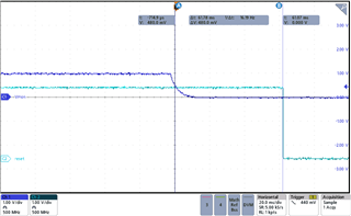
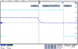
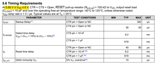
For detect time delay (td-sense), for example, when CCTS_EXT: 1μF is used, there is a slight difference between the value on page 5 of the data sheet and the calculation formula on page 14.
・Page 5: 619ms
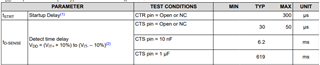
・Page 14: 655ms

Am I correct in assuming that the calculated value is a more accurate delay time?
Would you please let me know the reason why the difference is occurring?
Best regards,
Satoshi