This thread has been locked.

If you have a related question, please click the "Ask a related question" button in the top right corner. The newly created question will be automatically linked to this question.

UCC28C54: UCC28C54 won't start, strange WBDesign

Part Number: UCC28C54

Hi

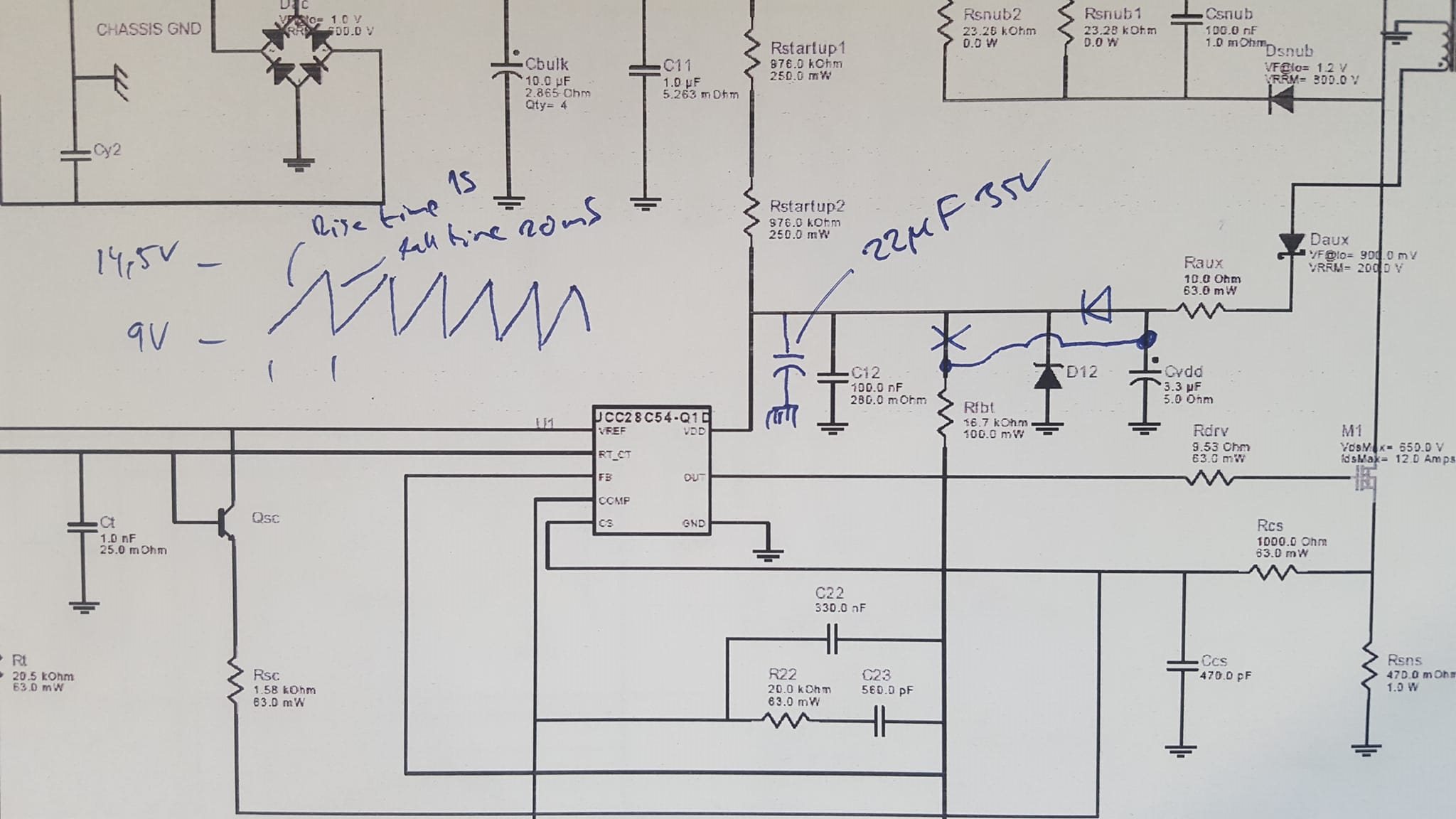
I used the WEBench designer for an AC/DC design using the UCC28C54, and got the design in the attached PDF.

I built it according to the design, but the UCC28C54 does not start.

Digging into the details I notice two things.

First of all, the voltage level at pin 7, VDD is around 3 V.  And that's not strange, as the DC level from the diode bridge is about 320V, and the Voltage divider made up of the Rstart resistors and the Rfbt+Rfbb resistors yields about 3V at pin 7 VDD.

The UCC28C54 needs 14.5V to startup.

Secondly, the UCC28C54 datasheet says that the capacitor Cvdd (or C12 in the datasheet) needs to be 22uF and that the IC not starting up is a common error caused by this capacitor being too small.

In the WeBenchdesign it is only 3.3uF.

So my question is - How is the WeBenchdesign supposed to work, and how can I get it to work?

Please note that I replaced the 3.3uF Cvdd with a 22uF capacatior, but it did not make any difference.

I also tried lowering the Rstartup resistors to give about 18V, but for some reason it seems not to go higher than 12.6V.

4010.WBDesign3.pdf

  • Hi,

    Is your schematics exactly as your attached - if not please send your schematics for review. Such support usually needs about a week. I will reply then.

  • Hi

    Yes, I followed this schematic exactly.

  • I have redesigned the VDD part according to the attached schematic.
    But it still doesn't work. I get a ramp up to 14.5V where the UCC28C54 obviously tries to start, but the voltage rapidly drops to 9V where the UCC28C54 obviously shuts down and the ramp restarts, and then this repeats, as drawn in the schematic. 

    Please advice!


  • Hi,

    Please provide the schematics for your converter not just portion it. After receive that I will have a review.

  • The full schematic BOM etc is in the PDF in the original post.

  • Hi,

    Can you change Raux = 0 then retest to see if operation can continue without VDD up and down?

    Also can you provide the waveforms of OUT pin when VDD reaches 14.5V and near by?

  • Hi

    I have attached a series of waveforms, all using the redesigned setup above.

    As can be seen, there is no output around 14.5V, or during the 20mS it takes for the voltage to drop to 9 volts. 

    I can however kick-start it by injecting 16 volt over a series resistor and diode to VDD, but even then it takes about 1 second for it to start operating. I added a waveform of this scenario too. Once it is operating, the injected voltage can be removed and operation continues, so this is a start-up problem only.7762.waveforms.zip

  • Hi,

    did you try setting up Raux = 0 to see if the converter can work ? What is voltage waveform at Daux from AUX winding?

  • Since there is no output at all, and hence no auxiliary voltage, I did not. Once the circuit gets going, it keeps working.
    If you really think it will make a difference, I can give it a try. 

  • The waveform at Daux from AUX winding is flat 0V.
    Once I inject voltage from external PSU and the UCC28C54 kicks in, the AUX voltage is fine. You can see it in the last waveform image I attached above.

  • Here's the waveform where I inject voltage to VDD from external PSU, then the curcuit starts operating. As you can see, there is no AUX voltage what so ever before the UCC28C54 starts operating, which takes about one second after 14.5V is reached. So I guess the real question now is - Why does it take 1 second for the UCC28C54 to start regulating after 14.5V is reached?

  • Ok, so I found another error in the WeBench design, and fixed it. Finally the design "works", or, well, starts up and generates a voltage.

    My original question remains, though - How is this webench design supposed to work?

    Because, as far as I can see, there's no way VDD can reach above UVLO Turn-on, and on top of that, the soft start is just so off the circuit will never start up anyway even if VDD reached 14.5V.

    My learning from this is to stay away from the WeBench design tool. 

    But now I am a bit worried, what more in this design is off? 

    It's said this design is about 90% efficiency. How trustworthy is that, when it contains blunt errors like these?

    I really would like an explanation from TI on this. Is this what I can expect from a TI design tool?

    Because it says on the Webench web page

    " The environment gives you end-to-end power supply design capabilities that save you time during all phases of the design process."

    It sure as h... didn't save me any time. On the contrary. And now I have to work through every little detail of the design to make sure there are no other "mistakes" built in by the design tool. I would have been much better off designing it from scratch myself to begin with.

  • Hi,

    It looks the soft start capacitor value C21 too high which requires very long soft start time so VDD capacitor cannot store energy enough to wait that much time.

    Webench is really a tool to help start. You would need to check every and all circuit in your bench test. 

  • Then you really shouldn't market it as something it is not, and instead put a warning sign that it produces designs that are totally wrong.
    And the support here wasn't to any help either.

  • Hi,

    Support here is to help find or make suggestions to your debugging. Webench is for starting point and its initial design needs bench debugging to make work and tune up to meet the specs.