This thread has been locked.

If you have a related question, please click the "Ask a related question" button in the top right corner. The newly created question will be automatically linked to this question.

LMR51420: LMR51420 Radiation Emission Exceed Limit

Part Number: LMR51420

Hello,

  We use the LMR51420 to generate a 5V voltage, the input capacitor is 22uF, the output capacitor 22uF. while the Inductor is 4.7uH.

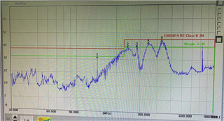
when we do EMI radiation test, we found that EMI value more than limit, after we debug several times, we still can't pass. the layout followed the suggestion on the datasheet.

Whether anybody had this kind of issue before? thanks

  • Hi, emi problems can be an issue with DCDCs. 

    If you would like us to provide assistance on how to improve the EMI of LMR51420 could you please provide:

    1. Schematic 
    2. Layout
    3. EMI scans
  • Thanks Marshall,

     LMR51420YFDDCR & LMR51420YDDCR have almost same result.

    to simplify the testing, only the 5V voltage generate circuit soldered.

    the wave point 2,3,4,5 is highest, mainly around 300Mhz, 

    there are still exist even increase the input capacitor and output capacitor.

    1. schematic

    LMR51420_Schematic.pdf

    2. Layout as the datasheet suggested;

    LMR51420_Layout.zip

    3. scan;

  • You are welcome.

    Thank you for sharing the additional information.

    I agree, your schematic and layout look good.

    The radiated scan you are sharing appears to show a spike at a frequency which the switch node usually rings at.

    There are a few things you can try doing to see if it can improve.

    1. Is L4 a fully shielded inductor?
      1. If not, I recommend choosing a shield inductor like coilcraft xgl series.
    2. You can slow the slew on the HSFET gate drive by placing a resistance in series with C3 and pin6.
      1. Start with 10ohms
    3. The SW node ring can have a snubber installed to damp the resonant ring
      1. Start with R=a couple ohm, C=22p