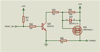
Hello, can I use this circuit to enable/disable the LMR14050-Q1 through its enable pin? Basically when RESET_SIG is low, Q3 turns off. Do I have to put a pull-down resistor (R6 here) between the enable pin and GND?

This thread has been locked.
If you have a related question, please click the "Ask a related question" button in the top right corner. The newly created question will be automatically linked to this question.
Hello, can I use this circuit to enable/disable the LMR14050-Q1 through its enable pin? Basically when RESET_SIG is low, Q3 turns off. Do I have to put a pull-down resistor (R6 here) between the enable pin and GND?

Hello, if the circuit you have is in-active and has a high mpedance, then the IC's internal pull-up with pull EN high keeping the device active. If you leave the pin floating the pin should be pulled high, so you would want a pull-down to de-activate.
Are you using this for an inverting output application? We have a simple level shifter circuit in the appnote link below.

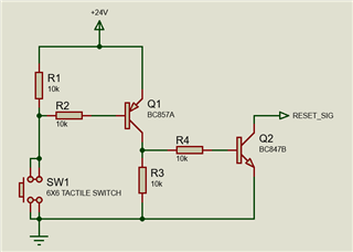
So all I need to do to disable it is just pull the EN pin to GND? Below is a sample circuit on how the RESET_SIG is produced. Would it be better to connect RESET_SIG to the EN pin to disable the buck converter?
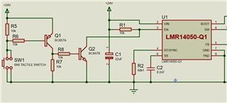
Maybe I should add a 10k resistor between VIN and EN pin to make sure that RESET_SIG that is connected to EN pin is one of 2 states, +24V or GND. What do you say?

hi, I haven't done an implemtation with a push button.
You need to ensure that you can pull EN above or below its threshold to active or deactivative the device. That is my recommendation.
I put the threshold value below from the EC table.

Would this work? It is basically the previous circuit that is now connected to the LMR14050-Q1. I cropped the other components out of the picture.

Hi, it looks like you are on the right track. I would recommend validating on the EVM or in a simulator tool to make sure it works before finalizing the design.