This thread has been locked.

If you have a related question, please click the "Ask a related question" button in the top right corner. The newly created question will be automatically linked to this question.

LM74930-Q1: PS ORing 50V350A

Part Number: LM74930-Q1
Other Parts Discussed in Thread: LM74930, LM74800-Q1, TPS4811-Q1, LM7480,

Hi!

I have pretty interesting task, not sure if possible.

That is my goal for now - get weight/size estimation.

Task is to design power distribution board with power supply ORing, total weight should be less 500g.Product is VTOL (drone)

ORing should be on 2 power supplies, one is 50V60A, second is 12s battery (max52V) 300A.

350A is expected during half minute, 200A expected during 1 minute, usually 50A.

Load is inductive - ESC + motors.

I also need to measure current. I think using shunt for 350A is not best solution, better use Rdson or hall effect based sensor.

I assume the best fit is LM74930.

I found out that best MOSFETs now for 60V capable to hold up to 40A continuous in ambient (no radiator)

NVMTS0D7N06CL looks nice

I think using more mosfets in parallel will take less weight, than applying radiator.

So for 50V60A

2*Q1+2*Q2 + LM74930

For 300A

8*Q1+8*Q2 + LM74930

Back mosfets I think will help me in case of BackEMF problems from inductive loads.

What do you think? I understand, MOSFETs in parallel have higher charge and so with the same current from driver it will switch slowly, but I think for this application it is ok.

For current sense I think to use hall based sensor, and for CSP-CSN I can provide voltage output throw resistive devider.

Will this work? I didn,t see problems from internal schematics for current sense block

Ye, looks crazy, but give me honest feedback

Thanks.

  • Hi Stas,

    Your understanding is correct that higher number of MOSFETS will take more time to switch. If it's okay for you, you can use it. If you do not want to use RSENSE to measure current, we don't have any controller to measure using RDS_ON. You will have to implement with external circuit. Now if you don't really want current related protection from the controller, you can consider using LM74800-Q1 as well. You can tackle back EMF with it.

    Your application is challenging with respect to compact size and high current majorly. From controller POV, I don't see any problem here.

    Regards,

    Shiven Dhir

  • I just wonder if it is normal practice to use up to 10 mosfets in paralel, maybe there is a problem doing so, but due to growth of rds_on of temperature, system looks self balancing. LM74800 looks nice, it is drone, i cannot have overcurrent protection, it will fall. My main concern is will this solution work with inductive loads (motors). Main consumer are motors, maybe only 10A to system. 12s battery is like 50V, I consider put 60V mosfet, also LM74800 is up to 65v. I am not really experienced guy in such big energy, is 10v gap enough? Considering on other side there is Li battery ready to eat backemf. Not sure I even will be able to use load dump, because if i select mosfet for 200v i think there will be like 50 in parallel for this current.

  • Hi Stas, 

    10 MOSFETs although seems very high but is achievable. Although you can fulfil your current requirement with a smaller number of FETs also, just need stronger FETs, since you are tight on space, I think you should choose a smaller number of FETs.

    I am unsure what you meant by "able to use load dump" "because if I select MOSFET for 200V I think there will be like 50 in parallel for this current."

    Do you mean that just be sure, you are considering 200V load dump configuration, if there are any transients? What does he following line mean?

    "50 in parallel for this current"

    Regards,

    Shiven Dhir

  • Hi!

    There is a "load dump" feature to prevent high voltage spikes on "load drop" event.

    200V MOSFETs have about 5 times hifger Rdson, so to implement "load dump protection" I would need to use 5 times more MOSFETs.

    If I use 10 parallel 60V MOSFETs so I will need to use 50 parallel 200V MOSFETs for load dump.

    Also I more curious about will this save me?

    I mean I want to control 50V300A with 60V MOSFETs and ORing controller. Will it work?

    How should I calculate voltage on FETs?

    How should I protect them against spikes?

    Is there any manual I can read to understand better how to control inductive loads?

    Stas

  • Hi Stas,

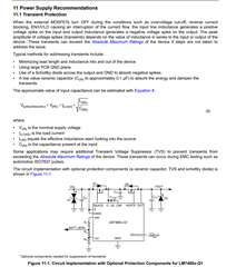
    While controlling inductive loads, you will see spikes during turn off of the motor. Datasheet talks about this and recommends adding a schottky at the output to clamp the negative side. To select input protection, you need to find out the level of transient first (if any)

    Controlling 50 MOSFETs does not sound idle. Stick to lesser number of FETs and add transient suppressor instead. 

    Regards,

    Shiven Dhir

  • But shottky is against negative voltage? Against spikes I would need TVS? Overvoltage will just break shottky, no?

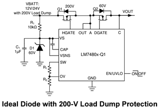
    As I understand Schottky D2 is needed in case I turn off power supply while motor running, so inductive load will take current from ground.

    And TVS D1 is needed in reverse situation: motor cut off and switch open. It will lead to increase voltage on input and TVS will eat this spike.

    Please correct me if I am wrong.

    I found out 200+V MOSFETs able to carry 15A, 20 MOSFETs in parallel is ok?

    Or better use ORing controllers in parrallel? Like 4xLM's with 5 MOSFET's each?

    Can I estimate level of transient before board production?

    Like if I have 50V system should I start with 60V MOSFETs or it is better to start with 80V?

    Or you suggest measure transient with direct connection from battery to motor?

    I expect it will dramatically change due to Rdson added in net, because wire connection is like microohms and right now I expect to see no transient with battery direct connection.

    I see some numbers of transient for 12/24V. Are there the same numbers for 48V or something like this?

  • Hi Stas,

    Yes, overvoltage can break schottky. For that you can set OVP feature in the device.

    TVS D1 is needed to clamp negative spike within the abs-max rating of the controller. 

    Further, I will let our high-power expert comment on this.

    Regards,

    Shiven Dhir

  • Hi Stas,

    I don't think you really need reverse current blocking feature here, so you need not consider an Ideal diode. Please consider TPS4811-Q1 once. You can start with 85V FETs and with time, improvements can be done, 85V should be a good starting point.  

    TPS4811-Q1 data sheet, product information and support | TI.com

    Regards,

    Shiven Dhir

  • Hi!

    Thanks for estimation.

    As I understand LM7480 can work as Ideal diode and Power switch according to pin setup.

    TPS4811 as I understand can act only as power switch.

    I can setup one PS with higher voltage to be power switch

    And second PS with lower voltage to be as diode in case of temporary peak current and so voltage drop on PS1.

    One PS is Li Battery and second PS is hydrogen fuel cell, so it obviously some alternator inside and that is  why I ask about load dump.

    85V is ok, but common transistor have grade 80V and 100V, I would start with 80V if you think it can succeed.

    Thanks

    Stas

  • Hello Shiven and Stas,
    I am not sure if it is appropriate to jump into your post, but i have a very similar application and would also like to determine the best solution. Shiven, please let me know if not appropriate to be here and i can create a new topic.


    Application is for a mobile robot power distribution board with the following components:

    • 2 x 2kW 48V batteries in parallel
    • 250 Amp continuous operation
    • inductive loads (6 ESC and Motors)
    • most likely using IAUT300N10S5N015 with a gate charge of 216 nC each


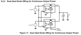
    I have considered both the LM74930-Q1 and  the TPS4811-Q1 for this application. My consideration of the LM74930-Q1 is that i would like to consider using it in a dual ideal diode ORing configuration as in this image. Both batteries would be at the same voltage so that i could hot-swap one battery and therefore remove the requirement to stop robot for charging.


    The following App Note was also inspiration for the design 

    https://www.ti.com/lit/an/sluaan7/sluaan7.pdf?ts=1715647314737 

    Requirements:
    Primary Battery disconnect:

    • Max 60VDC operating voltage
    • <10us short-circuit protection (bidirectional)
    • common source bidirectional switch support
    • Bidirectional current monitoring
    • Adjustable current limit (overcurrent protection)
    • Adjustable overvoltage protection
    • reverse polarity protection
    • short circuit protection
    • Pre-charge circuit

    Load (High-Side) Switching:

    • 4 x 50 Amp Motors (TPS4811-Q1)
    • 2 x 20 Amp motors(TPS4811-Q1)

    Can you please provide some insights into the benefits of using the TPS4811-Q1 over the LM74930-Q1 for my application?

  • Hi Zoran,

    Welcome to E2E! 

    Can you please post a separate thread to have a focused discussion on your topic. though it is similar, the follow-up questions may go in other direction.

    TPS4811-Q1 is mainly to drive parallel MOSFETs in high current applications -> strong gate drive of 4A Vs few mA for LM74930-Q1. It has 100V support vs 70V for LM74930-Q1.

    LM74930-Q1 was mainly designed to handle ISO pulses in automotive application where active reverse current blocking is needed.

    Best Regards

    Rakesh

  • Hi Stas,

    Please continue and reach out if there are any follow-up questions.

    BR,

    Rakesh

  • Thanks for the prompt reply Rakesh, I will create a new thread for further discussions.

  • Thanks Zoran

    Your task looks familiar to mine, I will also subscribe to  your net.

    Stas