This thread has been locked.

If you have a related question, please click the "Ask a related question" button in the top right corner. The newly created question will be automatically linked to this question.

LMR14050: output ripple during the soft start

Part Number: LMR14050

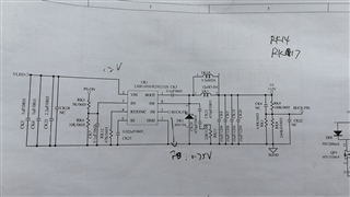
My customer was using LMR14050 for the below application:

Vin=24V, Vout=12V/ 2A.

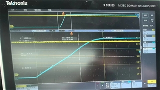
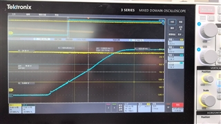
They found the voltage output showed some unexpected ripple/spike during the soft start, with full load startup.

The issue was found if using the CC mode for the electrical load, and it did not show up if using CR mode. But their system tests all required CC mode setting.

Could you please help check the possible suggestions for them?

The inductor they used is 12uH.

  • Hi Aki,

    Thank you for providing your screenshots and schematics. I reviewed your issue and have pinpointed some potential issues:

    When an E-load is in CC mode, it will still demand high current even when the input is still low, i.e. at startup and the device cannot support this until it's input voltage is at a high enough level. This can lead to voltage spikes and abnormalities during startup, as are shown in your waveforms. An E-load in CR mode will not do this, and this is potentially why these spikes are not as apparent on your startup when using CR mode. To help with this, TI recommends 4.7 to 10 uF of input capacitance as well as a high frequency capacitor placed as close as possible to the device input to smooth out the signal on input. Please see section 9.2.2.6 in the datasheet for more information. 

    I will note too that the application curves show similar ripples on startup, so this is not entirely abnormal behavior. I have included them below for your convenience.

    Regardless, if you would like to reduce the size of these spikes, increasing the input capacitance would be a good step to smooth out this startup curve. 

    Thank you,
    Joshua Austria

  • Hi Joshua,

    They tried to add another 47uF electrolytic capacitor, but it did not help.

  • Hi Aki,

    Thank you for trying that. Did you attempt to increase the amount of ceramic capacitance? Please ensure that the ceramic capacitance is not larger than 10 uF. 

    Additionally, what is the voltage rating of these capacitors?

    Thank you,

    Joshua Austria

  • Joshua,

    They just tried to add the electrolytic capacitor. 

  • Hi Aki,

    Please have them increase the ceramic capacitance to have it between 4.7 and 10 uF. Additionally, can you ask them what is the voltage rating of these capacitors? For a 24 V input TI recommends a 50-100 V rating for input capacitors to ensure that derating does not occur which would affect performance.

    Thank you,

    Joshua Austria