This thread has been locked.

If you have a related question, please click the "Ask a related question" button in the top right corner. The newly created question will be automatically linked to this question.

TPS546D24: TPS546D24 Probe Point

Part Number: TPS546D24
Other Parts Discussed in Thread: , , TPS546B24A

Hi Team,

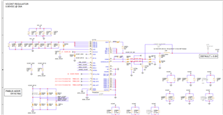
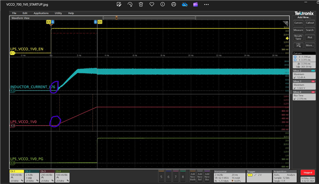
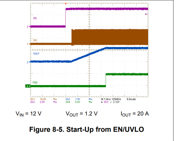
I am starting DVT of my board and want to test the transient and ripple of Buck Regulator(TPS546D24).

I just want to check which one be the right place to probe at  the output cap of Regulator or Nearby to the Decoupling CAP of FPGA?

It Seems Loop Incuctance will be different in both the above cases.

What slew rate should be set for Input Voltage of 12V to 0.8V@30A?

Please suggest.

Many Thanks

Rajat

  • Hi Rajat,

    Are you using the TPS546D24 or TPS546D24A? If this is for a new design, I would recommend using TPS546D24A (or TPS546D24S), which is a newer version of the TPS546D24. 

    The probe point should be at the regulation point where you connected the remote sense. So if you connected at the decoupling capacitor of FPGA, that's where I would recommend to probe it.

    There is not slew rate requirement for the input voltage. However, it is important to not exceed the abs max 16V and 19V for <2ms transient. 

    Thank you,
    Tomoya

  • Hi Tom,

    we are using TPS544D24A.

    What should be the slew rate at load transient case ?

    How to calculate it ?

    Many Thanks

    Rajat

  • We are using TPS546D24A.

    Previous meesage has typo.

  • Hi Rajat,

    Can you please clarify what you mean by the slew rate at load transient and how to calculate it? Usually, these requirement (e.g., load step, slew rate, transient response undershoot/overshoot) comes from the customer based on the load they're using (I believe it's FPGA in your case).

    Thank you,
    Tomoya

  • Hi Team,

    Can you please review attached 2 Waveform at start-up condition.

    VIN-12V

    Vout-0.8V

    Load Current -20A

     Frist case BW- 20Mhz for channel -1

    Second case BW- 1Ghz for channel -1

    Voltage Measurment at  Bulk Output cap of Voltage Regulator.

    I am seeing more Noise on output voltage at 1 GHZ BW.Should we worry about it?

    I am seeing small glitch on Inductor current start-up?What can be the cause of this?

  • Attached SCH for refrence.

  • The probe point should be at the regulation point where you connected the remote sense. So if you connected at the decoupling capacitor of FPGA, that's where I would recommend to probe it.

    TOM,

    Remote sense is located at nearby Decouplng cap of FPGA rail.Problem is all the caps are placed in bottom and CAP packge is 0402 which is placed in proximity  and its very hard to prpbe on the decoupling cap.

    Can you suggest some good method to probe on the cap?

    Many Thanks

    Rajat

  • Hi Rajath,

    Understood. When you measure the output voltage, it is recommended to use a tip-and-barrel measurement across the output cap to make the probe loop as small as possible for less noise pick up. What you are seeing is likely a noise pickup from the SW node because you're probe is acting as a loop antenna. You'd also want to use a BW limit (20MHz) for the output voltage measurement. You can measure across one of your 47uF caps. 

    The small glitch in the inductor current looks like a large-signal delay in the initialization of the error amplifier, which causes the loop to over-react and deliver too much energy to the output before it stabilizes around the nominal operating point. This is expected. 

    Thank you,
    Tomoya

  • You'd also want to use a BW limit (20MHz) for the output voltage measurement. You can measure across one of your 47uF caps. 

    To check start-up behaviour , do we need to limit the Bandwidth of Vout channel to  20Mhz? 

    I think BW limit is for ripple test case.

  • Hi Rajat,

    If you want to get a clean waveform on Vout I would recommend adding a BW limit whether or not you're looking at the ripple, but ultimately it's up to you and your preference on how much noise you can tolerate on the Vout waveform. BW limit gives you a better view of the waveform when there is noise on the waveform like the ones you've shown.

    Thank you,
    Tomoya

  • If you want to get a clean waveform on Vout I would recommend adding a BW limit whether or not you're looking at the ripple, but ultimately it's up to you and your preference on how much noise you can tolerate on the Vout waveform. BW limit gives you a better view of the waveform when there is noise on the waveform like the ones you've shown.

    Okay Thanks For the update.

    One more doubt I am using current probe which can support max 20Mhz BW.

    What BW we should select for current measurment thorugh indructor?

  • Hi Rajat,

    20MHz BW is perfectly fine for measuring the inductor current.

    Thank you,
    Tomoya

  • Hi Team,

    I have just complete thes start-up test and see some abnormality in the waveform.

    Vout- 1V

    VIN -12V

    MPN-TPS546B24A

    IOUT 10A

    we can see from the waveform once Enable is high,Vout and inductor current is starting little bit late. Why this is so? Please update.

    I checked the TPS546B24A datasheet and find out same case 

  • I can see some abnormility in inductor current sartup and shutdown behavior.

    Before Vout get stable Some displacement in Inductor current.

    Please suggest why this is happening.

  • Hi Rajat,

    The delay at startup is expected and it is also mentioned in the datasheet in the TON_DELAY register description. It is a time the device takes to initialize at every power-on. 

    Regarding your inductor current, the waveform should align with your output current (the load you are using). Based on your waveform, it looks like the device is sourcing full current (~10A) at around 500mV output voltage. This looks to me like you're using a Constant Current load that can draw the full current setting once it reaches it minimum threshold of around 500mV. 

    Thank you,
    Tomoya

  • Regarding your inductor current, the waveform should align with your output current (the load you are using). Based on your waveform, it looks like the device is sourcing full current (~10A) at around 500mV output voltage. This looks to me like you're using a Constant Current load that can draw the full current setting once it reaches it minimum threshold of around 500mV

    Thanks TOM , I will check thiis setting  in the E-Load. Yes its a constant current source.Cab you suggest how to corrct this?

  • Hi Rajat,

    If you want to correct it, you can try a resistive load setting on your E-Load. Most E-Load has a Constant Resistance mode. This may correct it. 

    Thank you,
    Tomoya