This thread has been locked.

If you have a related question, please click the "Ask a related question" button in the top right corner. The newly created question will be automatically linked to this question.

LM25085: Low efficiency, High dissipation, irregular switching behaviour

Part Number: LM25085
Other Parts Discussed in Thread: LM61460

Hi all,

I am having issues with a power supply design using the LM25085.

Specs:

- input voltage 24 V

- output voltage 5 V

- output current 0.6 - 5 A

Heat dissipation is 20% at 1 amp, 40% at 2 amps. The IC and the pFET are particularly heating up.

I observed an irregular switching behaviour on the gate of the pFET. Tried increasing the feed-forward capacitance for ripple pass-through up to 1 uF, with no considerable effect. Irregular switching is still present.

When designing a similar power supply of 12 V, the issue is less prominent. Also decreasing the input voltage, the heat dissipation decreases. It is therefore prevalent for lower duty cycles.

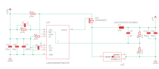
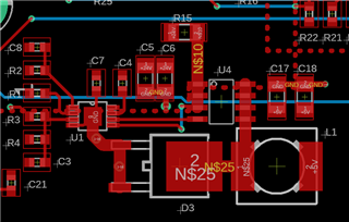
You can find attached the schematics and layout of the supply.

Thank you in advance for your help.

Best,

Oscar

  • Hello,

    It looks like you are using a VSSOP package device from the PCB layout IC footprint. 

    Most of the thermals go through the power planes (VIN, VOUT, and GND). In the PCB layout the GND looks like a simple small trace which will greatly bottleneck thermals.

    It is also mentioned in the datasheet that:

    As such I would suggest using the HVSSOP or WSON package since the exposed GND pads will definitely help lower the heat dissipation of the system.

    The HVSSOP should be a direct drop in replacement, you will need to make sure the top layer where the IC is soldered has a large GND plane to help with thermal dissipation.

    Regards,

    Jimmy

  • Hi Jimmy,

    thanks for your answer. It's a two layer PCB and the bottom layer is the ground plane. There is a via directly next to the IC's ground pad.

    I do not need to be able to dissipate more heat as stated in the datasheet, I need to eliminate heat dissipation because the efficiency now is ridiculously low. It has to do with irregular switching behavior. I don't observe a clean square wave, instead, there are multiple irregular spikes within a period.

    Best,

    Oscar

  • Hello Oscar,

    How much output capacitance do you have on the 5V output rail? It looks like you only have 2 x 10uF and depending on the voltage derating, it will be less than expected.

    Have you tried increasing the output capacitance? I'd suggest adding another 2 x 10uF and retest for stability, since you mentioned the switching behavior is not clean square wave.

    Regards,

    Jimmy

  • Hi Jimmy,

    I actually reduced the output capacitance to increase the ripple. Found a good combination of passives by decreasing the operating frequency. Now the efficiency is at 77% at 2 amps. Hopefully changing diode and with a slightly bigger inductor can bring it to 80-85%. First time I am having so many issues with a DC/DC.

    Best,

    Oscar

  • Hi Oscar,

    This device is an asynchronous buck controller and most of the power dissipation may be due to the external inductor and schottky diode.

    Note that the power dissipation through the schottky diode happens during the device's switching off-time and the average power dissipation is characterized by the following equation:

    As such when changing diode, please find a part that has the appropriate voltage rating and as low of a forward voltage to minimize dissipation.

    For inductors, try to pick lower DCR value parts so that conduction losses are minimized.

    Otherwise if you are open to changing to a new device, you might be interested in using the LM61460 synchronous buck converter.

    Regards,

    Jimmy