This thread has been locked.

If you have a related question, please click the "Ask a related question" button in the top right corner. The newly created question will be automatically linked to this question.

UCC28019A: The IGBT of the switch tube is damaged

Part Number: UCC28019A

The schematic diagram of the PFC part is as follows.Design requirement: AC220V/50Hz input, output DC 390V 3A, switch power transistor IGBT specification is 650V 20A. Currently, testing has found that the circuit will burn out the IGBT. Can you help find the cause and solution? Currently, I think it is caused by excessive current. Looking forward to your reply. Thank you~
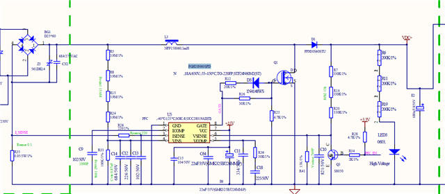
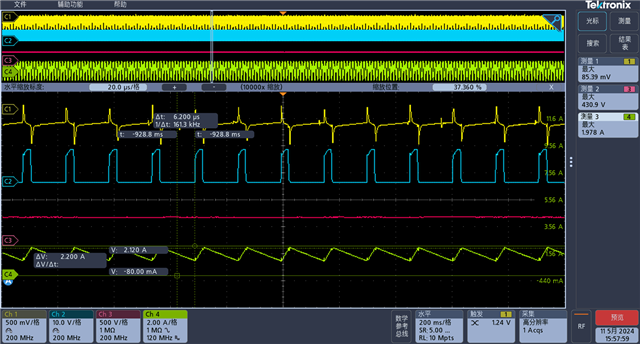
CH1:ISENSE     CH2:GATE    CH3:BUS voltage    CH4:BUS current

  • Hello Colin, 

    I assume that the FGH20N60SFD IGBT has replaced the Si MOSFET at Q1 in the schematic. 
    I think the cause of IGBT failure maybe overheating, but not by excessive current.  

    3A x 390V = 1170W output power.  At 220Vac input, I estimate Pin to be about ~1210W or so, and peak AC input current would be about 7.78A.

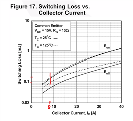
    From Figure 17 of the IGBT datasheet, total switching energy per cycle is about ~0.24mJ at 65kHz, which results in 15.6W switching loss at the line peaks. 


    Of course, the losses drop at lower current during the line cycle, so actual average switching loss is not so high, but conduction loss is added to this.  
    Also, for Rg other than 10ohm, Figure 16 indicates how switching losses vary for other Rg values.  
    I did not calculate conduction loss, but I suggest that you review the temperature rise of your IGBT to make sure it stays under control. 

    Note: if your conduction loss is much lower than your switching loss, then I suggest to choose a smaller IGBT to trade off more conduction loss for less switching loss. 
    Conduction losses drop as load drops, but switching losses depend only on frequency and do not drop at light load. 

    Regards,
    Ulrich

  • Thank you for your reply.

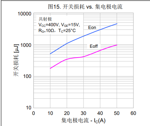
    At present, the IGBT has been replaced with SGT30T60SDM1P7 with 650V 30A. The switch loss is shown in the figure below. A serious phenomenon occurred during previous tests, such as diode D1, IGBT Q1, and Risense R35 and ISENSE PIN all being damaged; After re soldering and testing for a period of time, the IGBT still burned out, while other components did not. What may be the reason for this? Can replacing the IGBT solve the problem? Currently, the IGBT alternative is RGW40TS650D

    Thank you~

  • Hello Chen, 

    It looks like you replaced a big IGBT with an even bigger IGBT with approximately 3X higher switching losses.  
    I think you missed my point.  I am suggesting to choose a smaller IGBT to reduce switching losses. 
    I also suggested to monitor the temperature rise of the IGBT so that you can reduce or shut off power before it fails.  
    Please reread my last reply carefully. 

    When the new, larger IGBT fails, it may fail in such a way that the other components do not see excessive stress and do not get damaged.
    The smaller IGBT probably fails in a way that passed overstress to the other parts.  

    Ideally, you will find an optimally-sized IGBT that does not overheat and does not fail so that other components also do not get overstressed or fail. 

    Besides minimizing total power loss in the IGBT (conduction + switching), make sure that the heatsinking for that IGBT is sufficient to keep its junction temperature at a reliable level.    

    Regards,
    Ulrich

  • Hi Ulrich,

    Thank you for your reply.

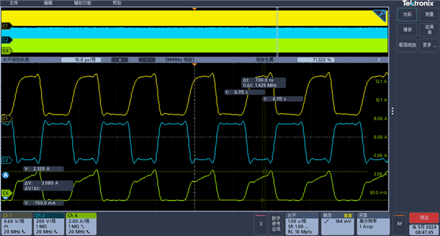
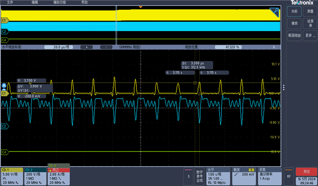
    Figure 1 shows the driving waveform CH1 (full load) of IGBT RGW40TS65DGC13 as a switch;

    Figure 2 shows the driving waveform CH1 (full load) of IGBT FGH20N60SFD as a switch;

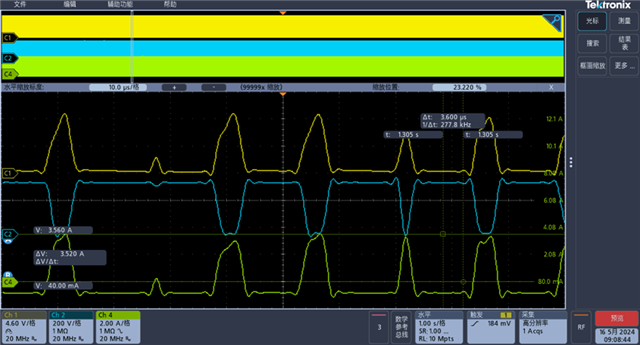
    Figure 3 shows the driving waveform CH1 (light load) of IGBT STF24N60M2 as the switch;

    At present, it has been found that FGH20N60 has a partially low driving voltage. Will this small driving voltage cause damage to the IGBT? The driving voltage waveform of RGW40T65 is relatively stable, and STF24N60 has not tested the waveform at full load; I have also seen the temperature rise of IGBT, and the impact should not be significant

    Can you provide some troubleshooting suggestions?Thank you~

    Figure1: IGBT RGW40TS65DGC13       CH1 Vgate   CH2:VDS  CH3:ISD(source-grounds)

    Figure2: IGBT FGH20N60SFD       CH1 Vgate   CH2:VDS  CH3:ISD(source-grounds)

    Figure3: IGBT STF24N60M2       CH1 Vgate   CH2:VDS  CH3:ISD(source-grounds)

  • Hello Chen, 

    Your waveforms are distorted due to aliasing effects from very low sample rate. 

    Your sweep is at 1s/div, so you capture 500AC line cycles in 10 seconds, then zoom to 10us/div. 
    The sample resolution is 10Mpts in 10s, which is basically 1 point per us.  Any details less than 1us in duration are lost.

    In a steady-state condition, there is nothing more to be found in 500 line cycles than in 1 line cycle.
    To increase sample resolution, I suggest that you capture 1~2 line cycles at a sweep rate of 2~5ms/div and the same 10Mpts.
    Then zoom in to examine the details of the various waveforms at various points along the line cycle.  

    The screen shots above do not convey useful information. 

    Regards,
    Ulrich