This thread has been locked.

If you have a related question, please click the "Ask a related question" button in the top right corner. The newly created question will be automatically linked to this question.

UC3879: CYCLE-BY-CYCLE CURRENT LIMIT - delay time

Part Number: UC3879

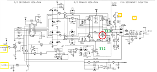
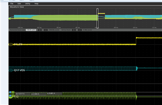
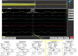
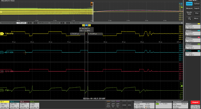
We are experiencing high failure rates for our Q17 (low side FET on the right leg) under close to short circuit conditions. We are observing the cycle-by-cycle current limit phase shifts Q15 (left leg) and begins conflicting with required transfer time between the two legs. Wanted to ask measure we can take to mitigate this issue?

  • Hello,

    I think your CS transformer is not setup correctly and you may not be sensing the true current in the H Bridge FETs.

    This is most likely why your FET is failing.

    Typically you sense the current in the input of the H Bridge and require a reset resistor to ensure the current sense transformer resets.

    The following link will bring you to an application note that goes through the step by step design process of a phase shifted full bridge including placing and setting up the CS transformer.  I believe you can use this information to properly place and setup the CS transformer. 

    https://www.ti.com/lit/pdf/slua560

    Regards,

  • We do have a configuration where we do a software monitor of current through DC_OC (of schematic) and if current is to high we disable through DC_EN (schematic). The design intentions are to implement the PWM UC3879 current limit for 12A for a more reliable protection in more rapid current rises.

    this scope capture is a current limit using our software to disable the PWM controller.

    We are evaluating output transformer characteristics from supplier, because we are seeing relatively higher current in the left leg transition (see below). Possibly the higher energy is causing a harder switch as the current limit phases shifts from the cycle-by-cycle current limit issue. Let me know if this an evaluation worth taking.

    below is a capture of the PWM UC3879N current limit with the cycle-by-cycle shift

  • Hello,

    Your inquiry is under review.

    Regards,

  • Hello,

    If one leg has more current than the other this would imply there is an issue with the transformer turns ratio not be correct.

    If this is the case the transformer manufacture needs to correct the issue for you.

    Regards,

  • we dissembled the transformer ratio and it is per our specification 

    We did change FETs with much lower gate capacitance and noticing charging/discharging issues at the waveform title "CAP" in blue of the pasted image

    but when the PWM begins to modulate for current limit you can see the issue gets worse and waveform in blue "CAP" does not reset (area pointed at with yellow arrow). can this be an issue where our DC blocking capacitor is not sized appropriately? currently at 470nF but will test with 2.2uF, let me know if this is worth investigating.

    much thanks for all the quick feedback

  • Hello,

    You actaully could have measure the voltages across the primary and secondary along with the currents in the secondary windings of the transformer to check the turns ratio.  You still may want to do this in circuit at 10% load just to make sure.

    Those current in the FETs should be identical and controlled to the same peak current on each leg.  Your current sense signal does not look correct either.

    The current sense technique your  using could be adding to the issue.  The following link will bring you to an application note that goes through how to place and setup a current sense transformer in phase shifted full bridge.  I believe if you fix this you might resolve your issue.

    https://www.ti.com/lit/pdf/slua560

    Regards,

  • much thanks for the feedback and understand our current sense technique will require reevaluation and will move forward with an R&D investigation on my end based on the info provided. 

    We are seeing improvement with adjustments to the Series capacitor on the primary winding of the output transformer. since this isn't specific to the Current limit, I will close my issue here but will open a separate discussion for UC3879N - Voltage control mode - series capacitor on the primary winding.