This thread has been locked.

If you have a related question, please click the "Ask a related question" button in the top right corner. The newly created question will be automatically linked to this question.

TPS55288: TPS55288 output side provide the external 5V power source

Part Number: TPS55288

one question,TPS55288 output side provide the external 5V  power source,Will it damage the IC function when input side not voltage?

  • Hi Vic,

    When Vin is zero volt, the device is in shutdown mode. External 5V will not damage the IC, but please take care of the abs max voltage rating on Vout is 25V.

    BRs,

    Bryce

  • Hi Bryce

    please help the check schematic,i will used the i2c controler out voltage 9V when input is 12V

  • Hi Vic,

    Below is my feedback.

    1. Add a 0402 ceramic capacitor in DC_IN_11 net.
    2. Maximum voltage rating is 20V. Make sure DC_IN_11 NET will not exceed.
    3. Make sure SCL and SDA pin is pulled up to VCC with 2.2kohm resistor.
    4. Recommend to add 2.2ohm(1206 package)+ 330pF RC snubber in SW1 and SW2.
    5. Can you provide part number of C5130 to C517? Recommend to use ceramic capacitor in C513-C516.BRecommend to put C517 after R1146.
    6. Recommend to add a 0402 ceramic capacitor in Vout pin and put it to chip closely.
    7. What is the package of R1146? Recommend to add two 10ohm resistor as EVM do.
    8. Will input voltage vary?
    9.What is the Isat of inductor?

    Regards,

    Mulin

  • 1. Add a 0402 ceramic capacitor in DC_IN_11 net.
    [Vic]done,please refer schematic
    2. Maximum voltage rating is 20V. Make sure DC_IN_11 NET will not exceed.
    [Vic]done,please refer schematic
    3. Make sure SCL and SDA pin is pulled up to VCC with 2.2kohm resistor.
    [Vic]done,i will pull up to DC_IN_11,right?
    4. Recommend to add 2.2ohm(1206 package)+ 330pF RC snubber in SW1 and SW2.
    [Vic]i don't have 2.2R 1206 resistor,4R7 1206  suggestion?
    5. Can you provide part number of C5130 to C517? Recommend to use ceramic capacitor in C513-C516.BRecommend to put C517 after R1146.
    [Vic]done,please refer schematic
    6. Recommend to add a 0402 ceramic capacitor in Vout pin and put it to chip closely.
    [Vic]i will put 1uf/16v MLCC,it's right?
    7. What is the package of R1146? Recommend to add two 10ohm resistor as EVM do.
    [Vic]R1146 is 1206 package,used the 10mohm current sensor resistor
    8. Will input voltage vary?
    [Vic]kepp to 12V/3A
    9.What is the Isat of inductor?
    [Vic]Isat=13A,Idc=10A

    another question,i will used i2c control,hardware should be how to setting? "vout(FB_INT)","COMP","LIMIT","CDC","MODE"

  • Hi Vic,

    1. Sorry to confuse you, I mean add a 0402 0.1uF/1uF ceramic capacitor in DC_IN_11 net and output.
    2. SCL SDA pin maximum voltage is 6V. So connect it to VCC or 3.3V.
    3. It is ok to use 4R7.
    4. Current "LIMIT","CDC","MODE"set is ok. Will you use internal FB or external feedback?
    5. In PD application, recommend to add two 10ohm resistor in current sense loop to filter noise. Please refer to following R7 and R9.


    6. As to COMP setting, I didn't find output capacitor(C513-C518) part number or datasheet. Please provide so that I can get ESR and effective- capacitance.
    7. Please refer to our layout guideline and send to us for review after it is finished.

    Regards,

    Mulin

  • Another issue ,we need to TI sample code for system Integrate,could you help to provide?

    function is 12V/3A input and 9V/2A  output

  • 1. Sorry to confuse you, I mean add a 0402 0.1uF/1uF ceramic capacitor in DC_IN_11 net and output.
    [VIC]done,refer to schematic

    2. SCL SDA pin maximum voltage is 6V. So connect it to VCC or 3.3V.
    [VIC]done,refer to schematic

    3. It is ok, to use 4R7.
    [VIC]OK

    4. Current "LIMIT","CDC","MODE"set is ok. Will you use internal FB or external feedback?
    [VIC]i will used external FB,if the fixed output 9V,HOW to the setting R1144/R1145?

    5. In PD application, recommend to add two 10ohm resistor in current sense loop to filter noise. Please refer to following R7 and R9.
    [VIC]done,refer to schematic

    6. As to COMP setting, I didn't find output capacitor(C513-C518) part number or datasheet. Please provide so that I can get ESR and effective- capacitance.
    [VIC]C513~516:FUKUI MURATA MFG. CO., LTD. GRM188R61C106MA73
    C517:attached file
    C518:YAGEO CORPORATION CC0402KRX5R8BB104

    7. Please refer to our layout guideline and send to us for review after it is finished.
    [VIC]attached file

     C517.pdf

  • Hi Vic,

    1. R1144=100kohm, R1145=15.4k.
    2. Recommend compensation parameters: R1140=15kohm, C520=15nF, C524=15pF.

    Regards,

    Mulin

  • Another issue ,we need to TI sample code for system Integrate,could you help to provide?

    function is 12V/3A input and 9V/2A  output

  • Hi Vic,

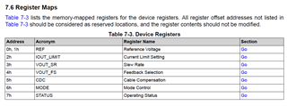
    Sorry that we don't have sample code. Resister maps are as follow.

    Regards,

    Mulin